 |
 |
 |
 |
|
To start with we require
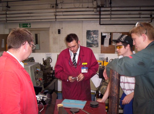
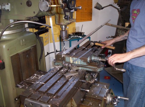
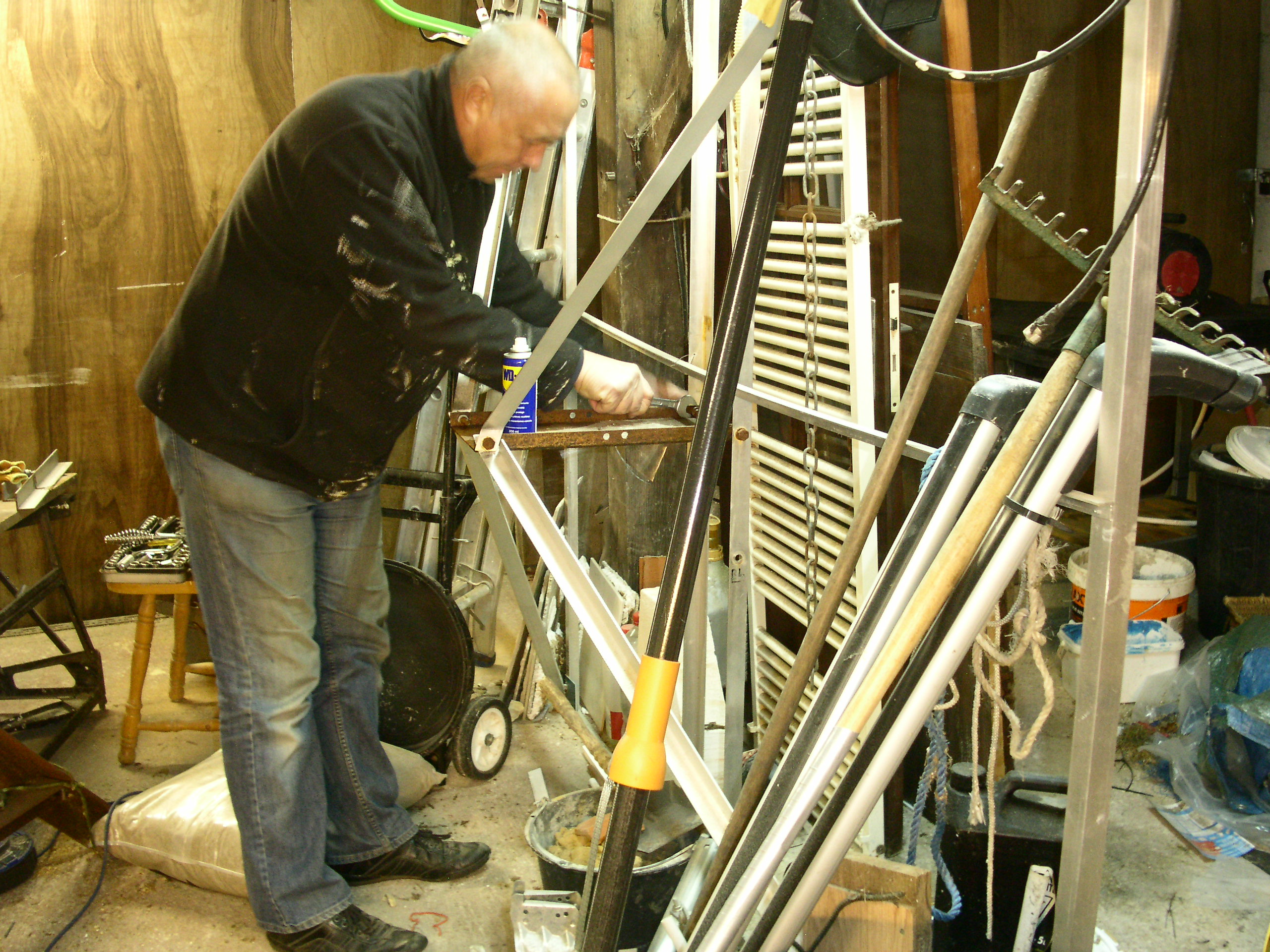
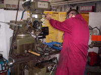
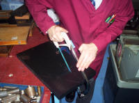
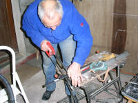
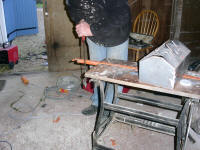
a sturdy tripod mount. here is my colleague Pete cutting up the 2"
angle iron for the legs. |
Must admit it's been a
while since I did this sort of thing. Working out which way
round to make the cut caused the brain to overheat |
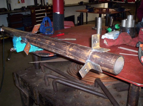
Here we have the main
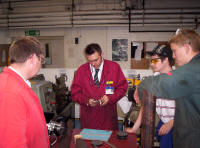
mast with the satellite tracker arrangement on the bench |
Jager 1224 supposed to
be good for a 2 metre dish |
 |
 |
 |
 |
|
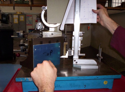
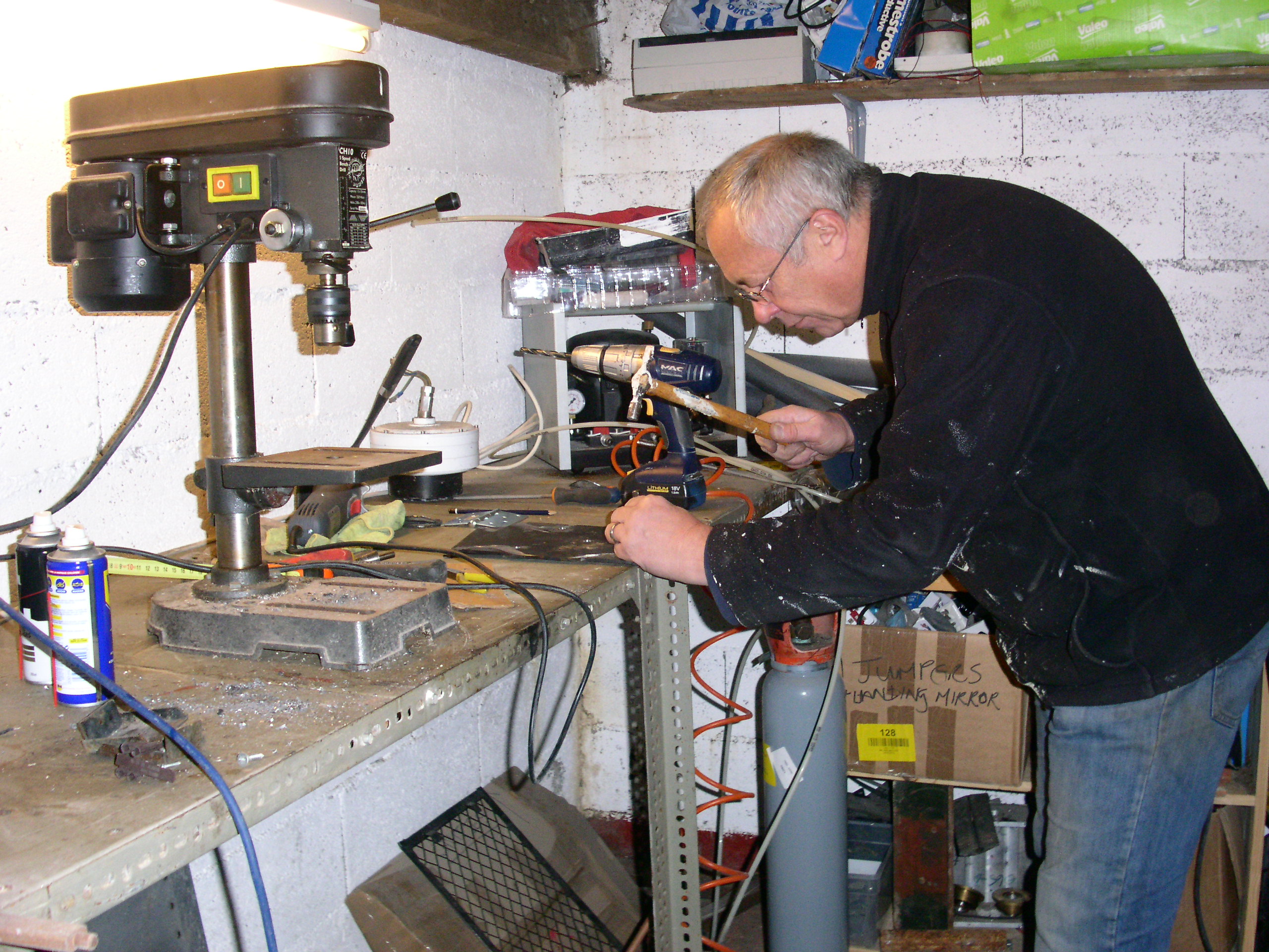
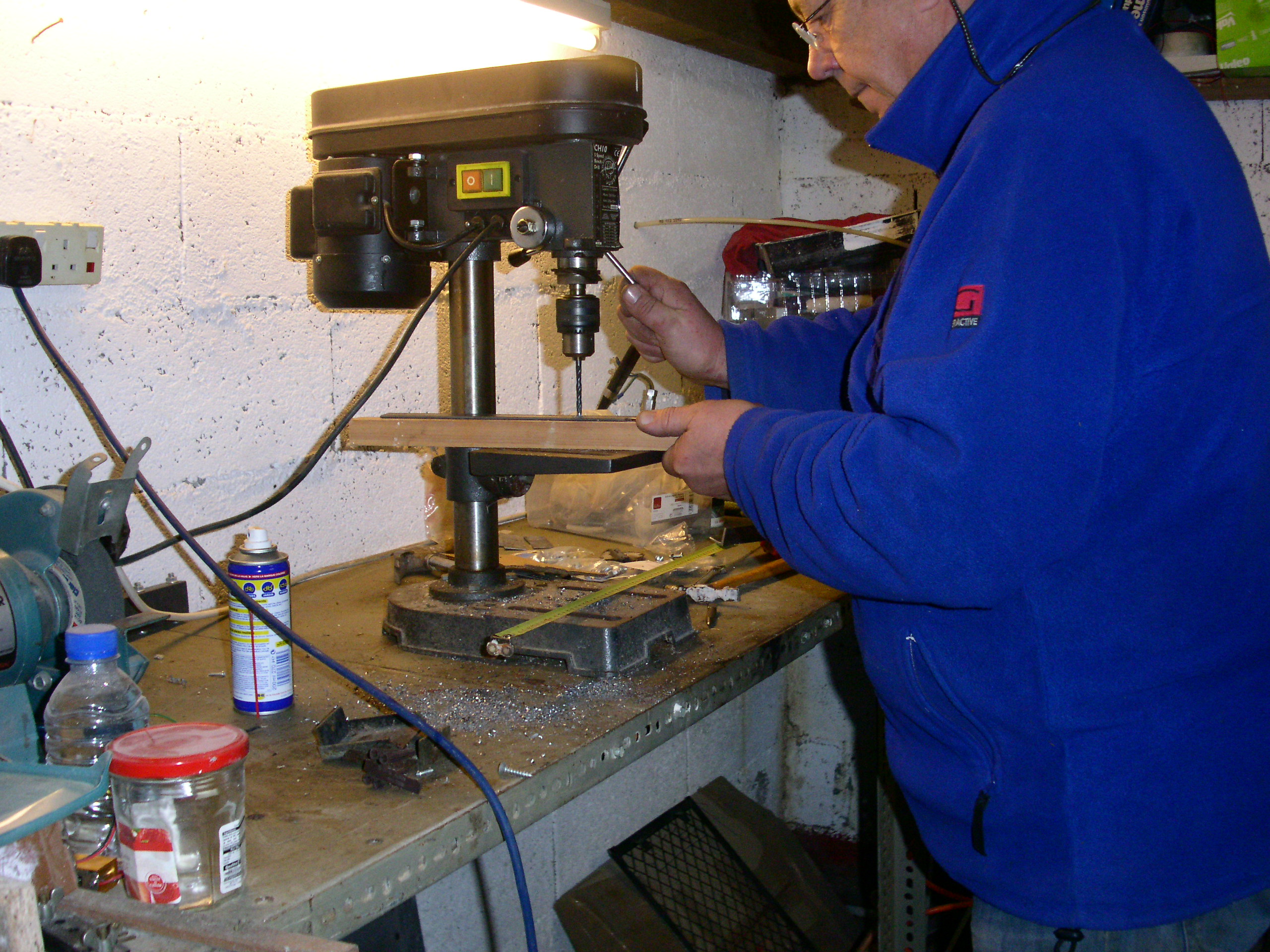
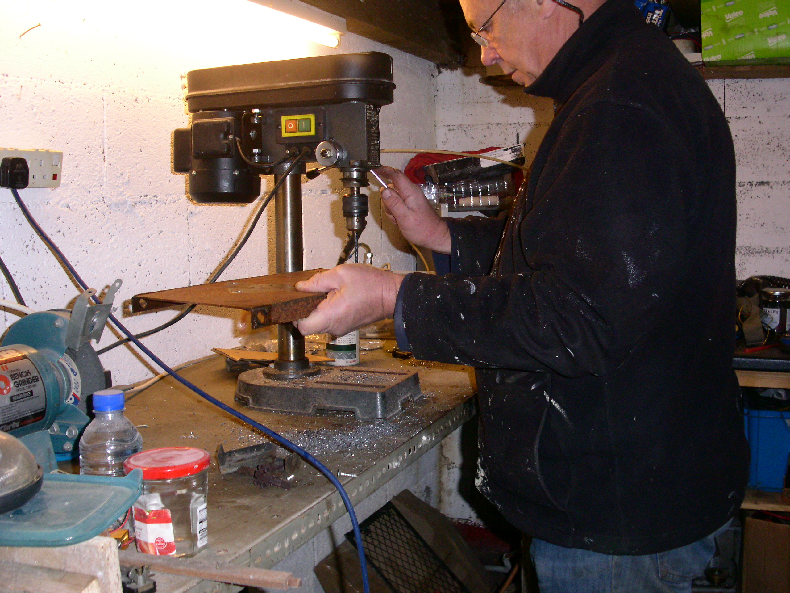
Pete drilling the fixing
brackets for the tripod legs which will be welded to the main support
tube |
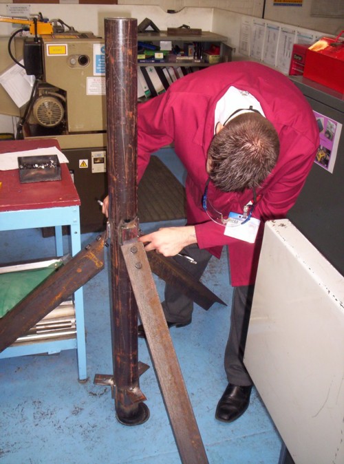
Pete checking the bend
angle of the brackets which Andy had bent up |
Post angle checking - a
slight adjustment called for |
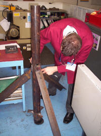
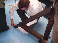
This is Harry, one of
our welding apprentices, practicing his telekinetic power of
levitation |
 |
 |
 |
 |
|
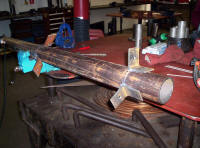
The main mast support
tube ready to have the brackets welded on |
Pete bolting on the legs
to the new brackets |
As it can get quite
windy in Cyprus we decided to add some braces |
Brace being drilled |
 |
 |
 |
 |
|
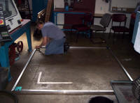
and ready for bolting up |
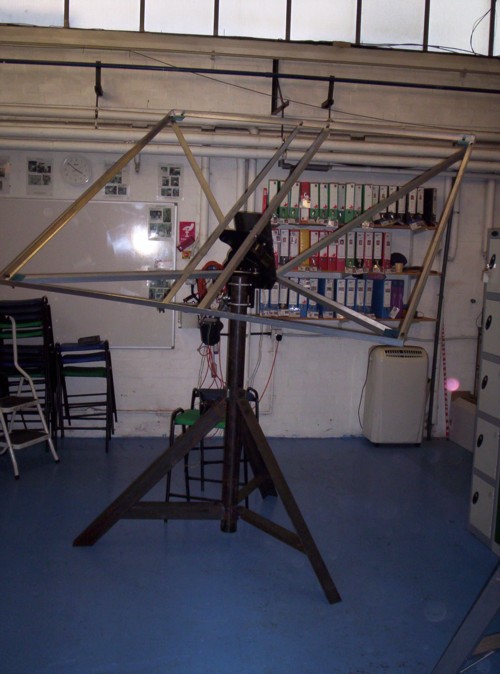
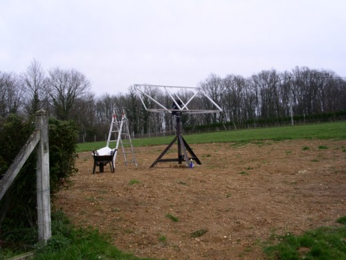
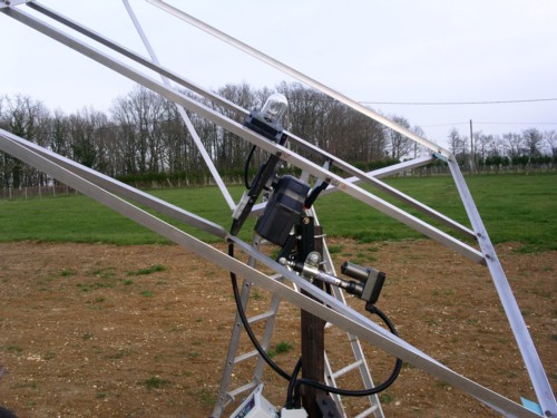
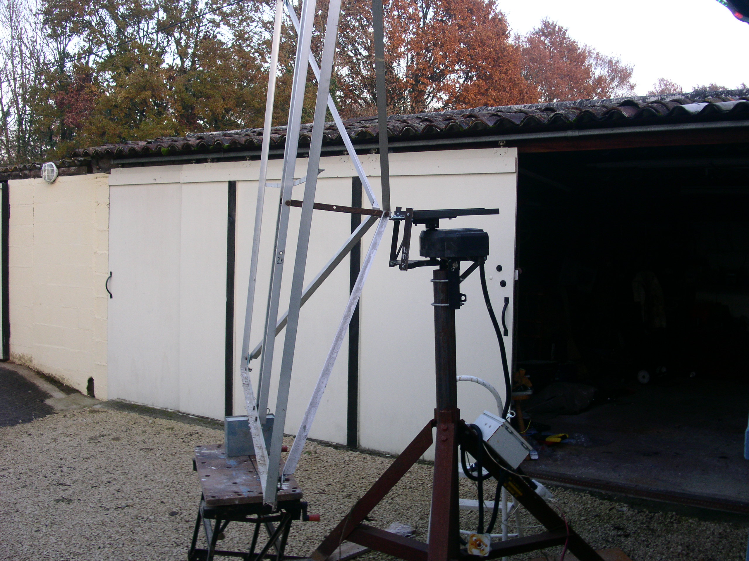
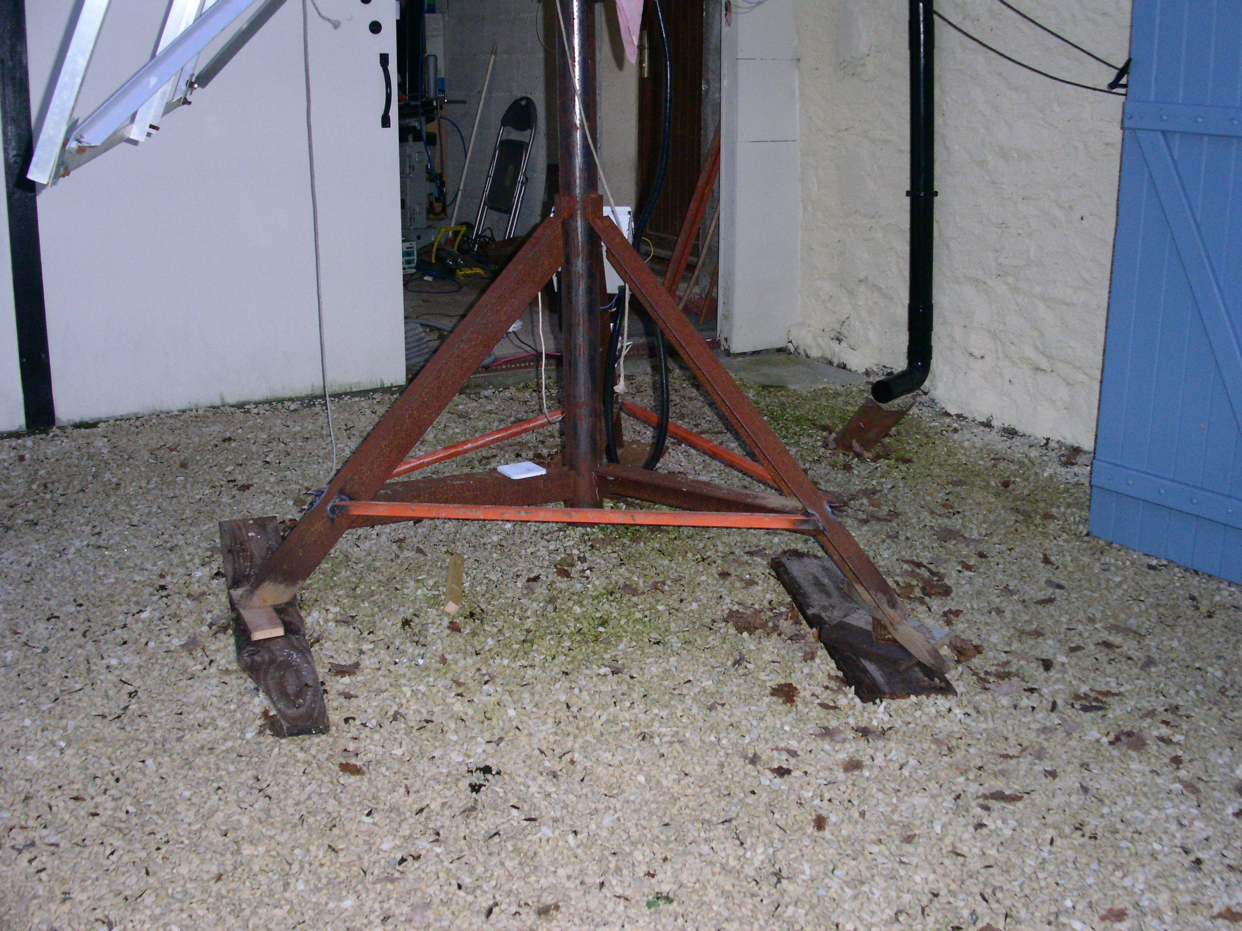
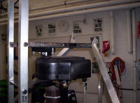
Tripod and main mast
with dual axis motor and the main stays of the solar panel frame |
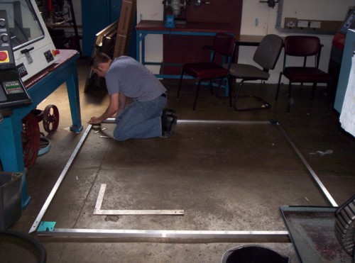
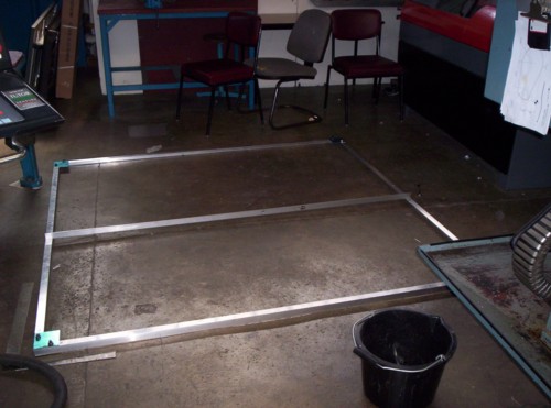
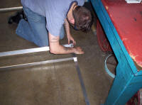
Pete fitting together
the main solar panel frame |
Wow, it does look big ! |
 |
 |
 |
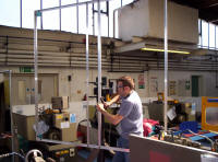 |
|
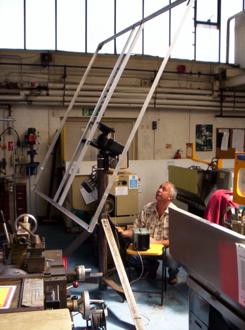
Main frame stays being
tested |
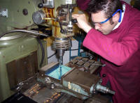
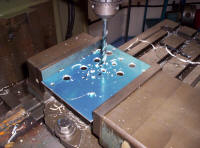
Final drilling |
and fixing |
prior to fixing to the
motor mount |
 |
 |
 |
 |
|
Who's a happy bunny -
First test |
OK, so we've got the
main metal bashing done. Time for the control bits. This
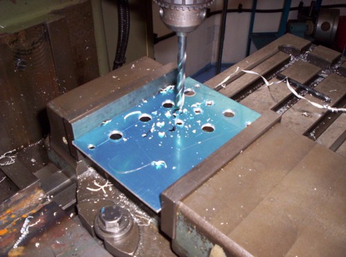
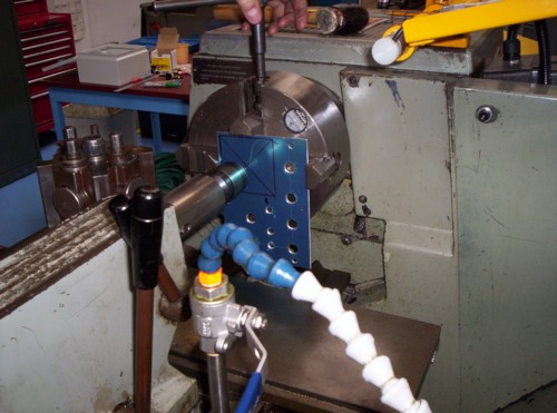
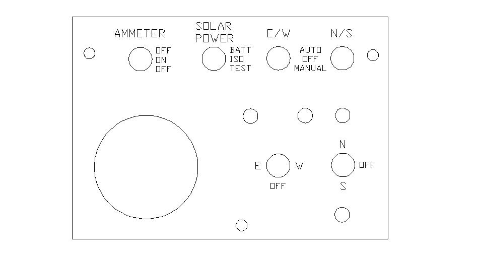
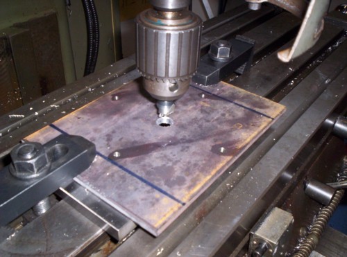
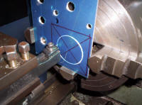
is the main control panel being marked out |
and drilled |
for the control switches |
 |
 |
 |
 |
|
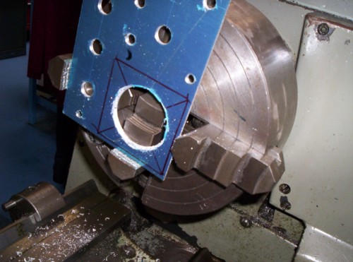
and this is how Pete
made the hole for the ammeter |
Saved us buying a hole
saw |
and was fun to watch as
well |
The panel was then
scanned to enable lettering to be produced |
 |
 |
 |
 |
|
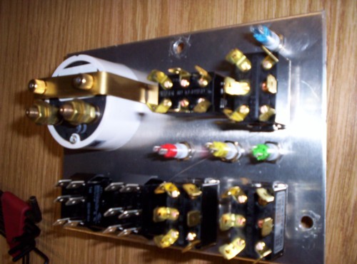
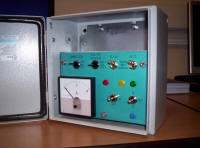
Panel with controls
fitted |
Template of front panel
graphics |
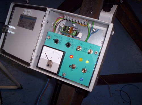
Diagram of control panel |
Panel complete with
controls and markings |
 |
 |
 |
 |
|
Back to the kitchen
table for the control panel wiring |
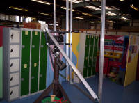
To stop getting bored we
like to swap jobs a bit. Here we are fitting the rear
strengthening stays to the main frame |
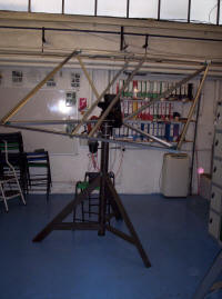
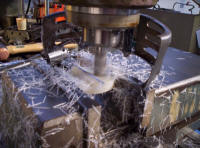
I thought cutting the
angle iron for the feet was mind boggling. These angles did my
head in |
But we managed it |
 |
 |
 |
 |
|
The frame tilted back to
track the sun at midday |
Time to swap jobs again.
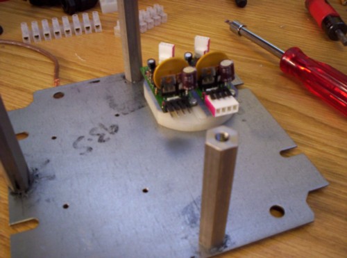
These two pcb's control the two motors that move the frame |
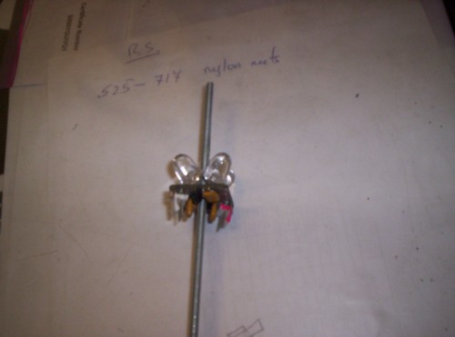
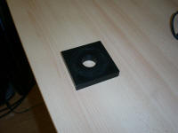
I wanted to mount them
properly so Pete made up a little nylon block |
What a mess it made |
 |
 |
 |
 |
|
Fit the first pcb |
then the second. Very
pleased with this. |
Back to the control box
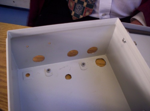
and time to do some more metal bashing making holes for the flexible
conduits |
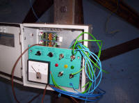
All holes in place(!!)
and component chassis mounted |
 |
 |
 |
 |
|
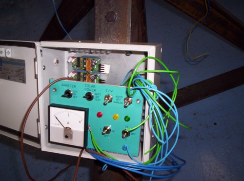
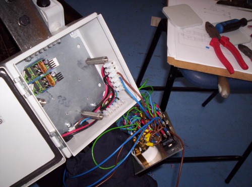
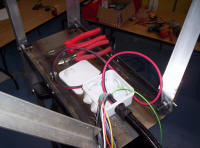
Another HXT birds nest
but it will look good with the door closed |
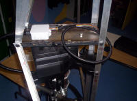
Time to fit the conduits |
and run in the cables |
for both control and
solar power |
 |
 |
 |
 |
|
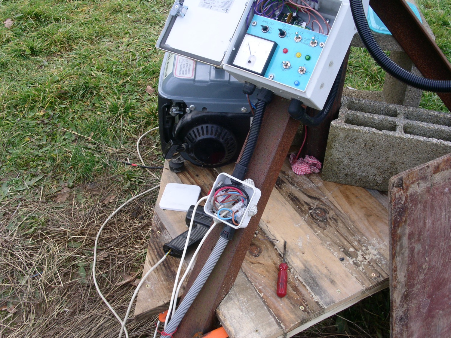
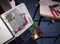
and start connecting it all together |
Not bad although not finished |
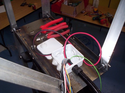
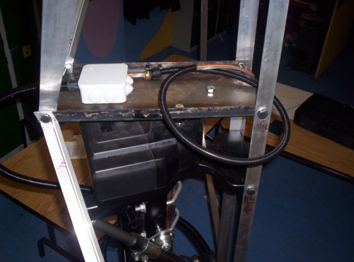
This box carries the
main solar power cables and the sun sensor cables |
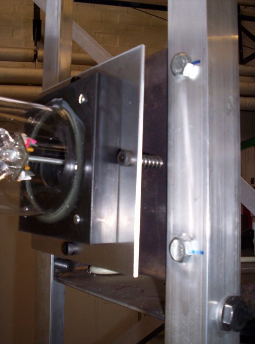
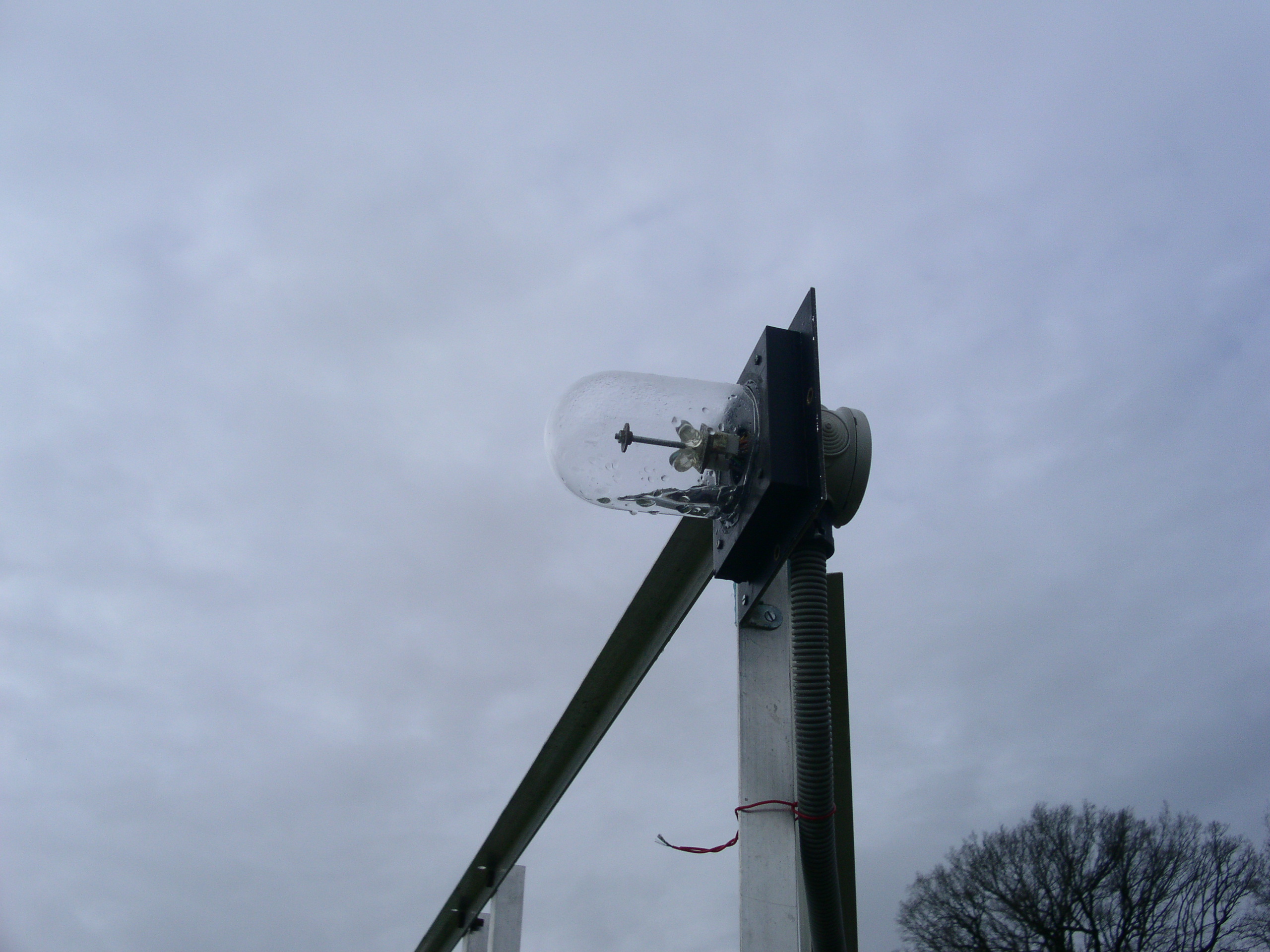
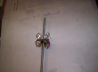
Part of the sun sensor
arrangement under construction |
 |
 |
 |
 |
|
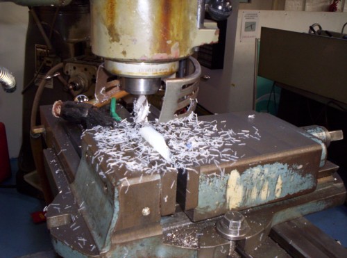
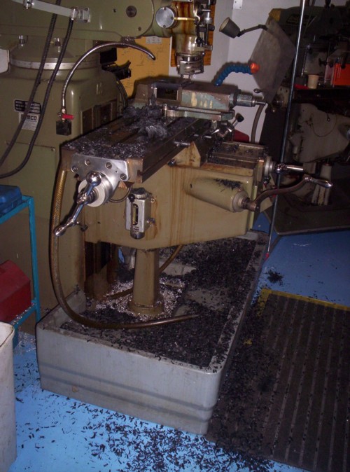
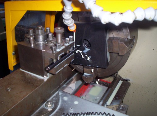
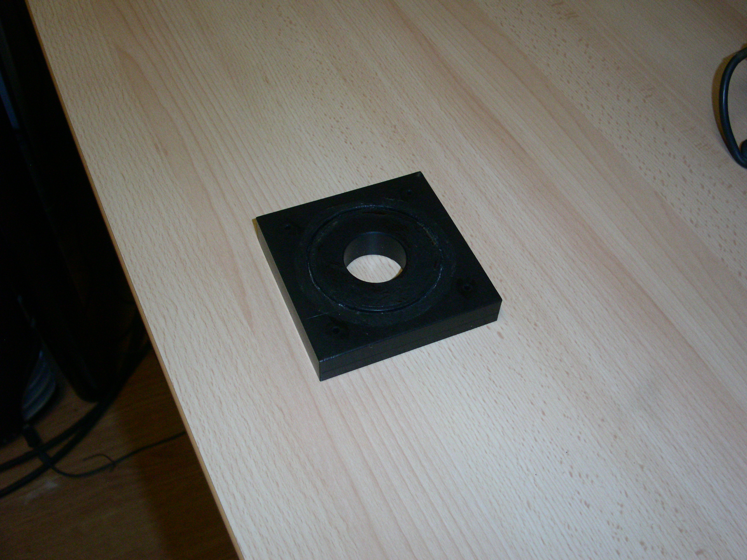
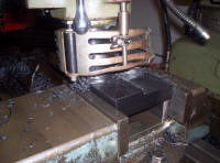
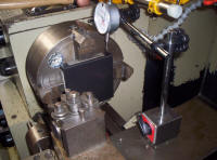
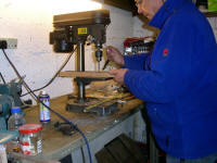
This is the mounting
block for the solar sensor dome being milled |
This made more mess than
the pcb mount |
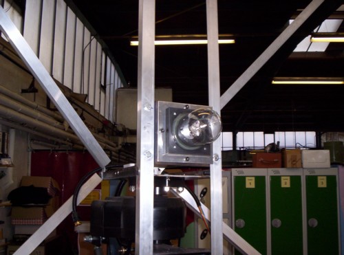
The sun sensor |
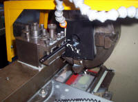
Mounting block being
machined |
 |
 |
 |
 |
|
to provide a hole for
the sensor cables |
and an undercut for the
dome |
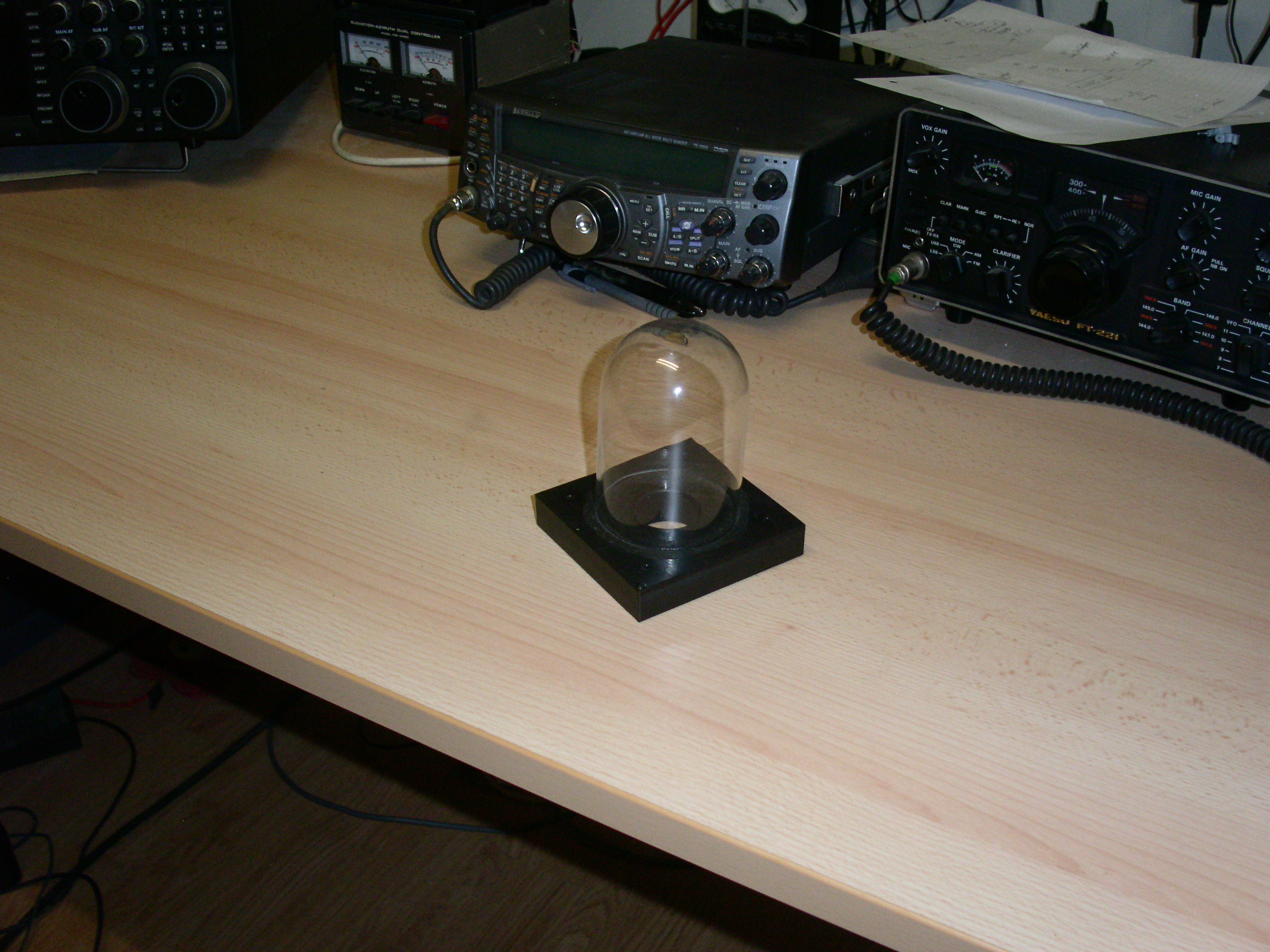
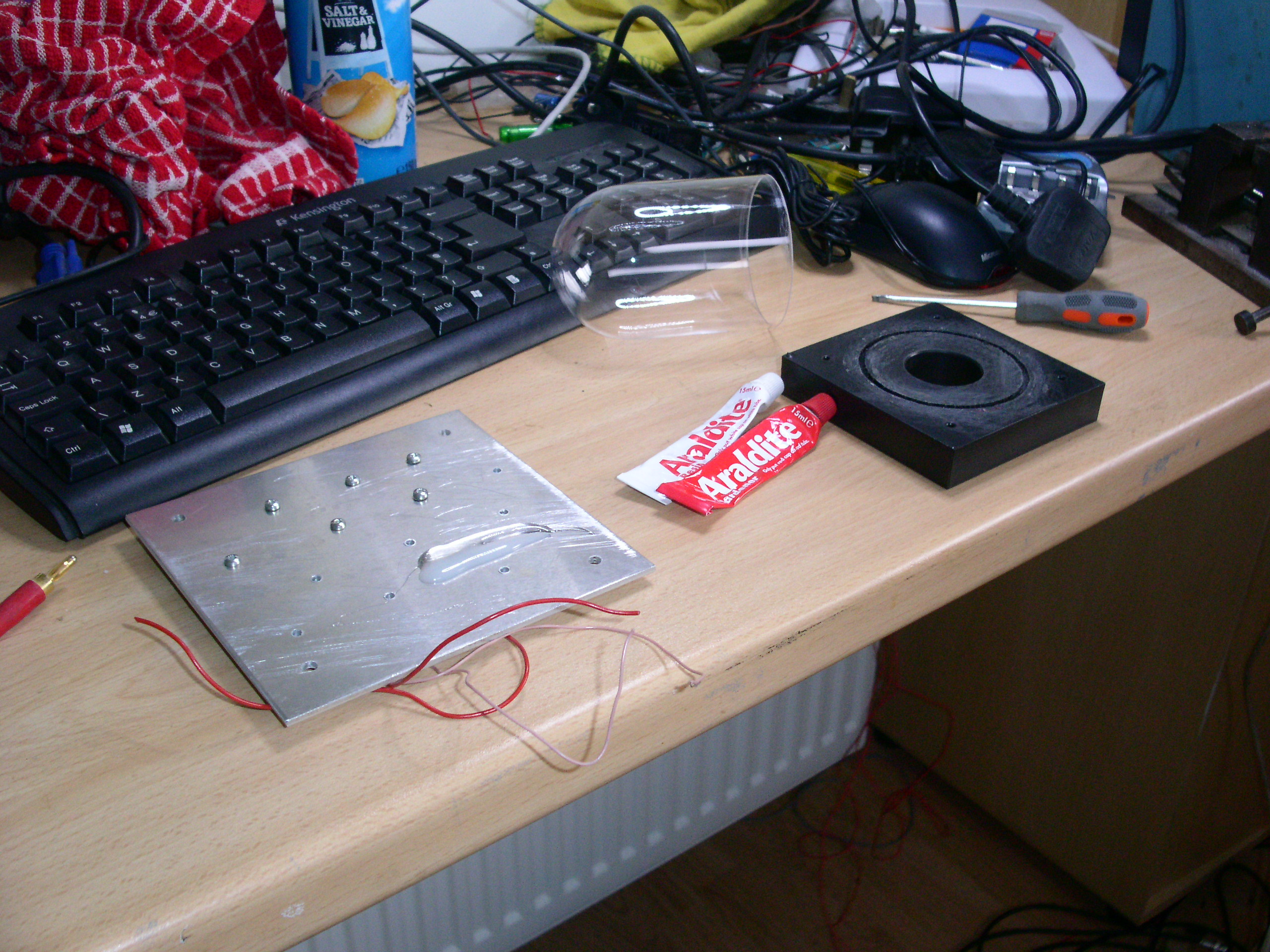
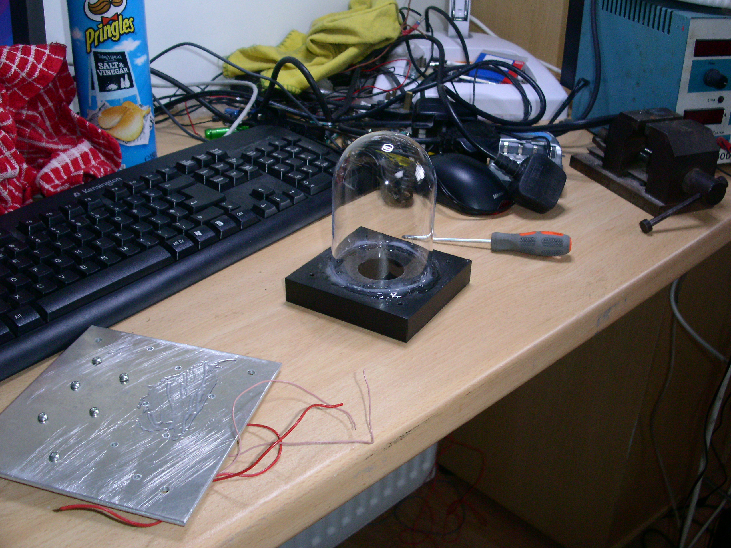
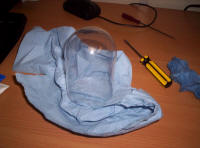
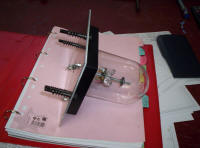
Here is the dome. Bought
on ebay |
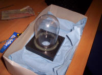
and glued into the
recess in the mounting block |
 |
 |
 |
 |
|
and with the senor array
fitted |
and mounted to the
adjustable aluminium plate |
that then fixes to the
main mounting plate. |
This provides
fine alignment of the sensor to the solar panels |
 |
 |
 |
 |
|
The sun sensor
arrangement fitted to the main solar panel framework |
with adjusting bolts |
NICE |
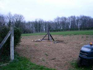
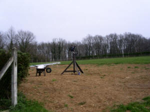
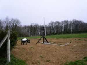
March 2011 France AT
LAST Time to put this thing back together again and put it to
work |
 |
 |
 |
 |
|
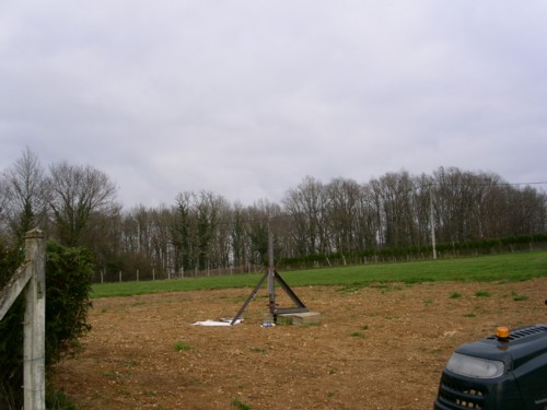
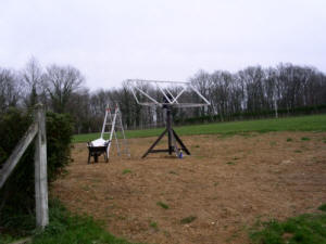
Some concrete blocks for foundations |
to reduce the chance of it blowing over
in the wind |
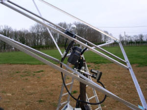
Fit the tracker motors |
then the solar panel framework |
 |
 |
 |
 |
|
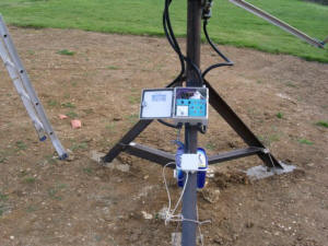
and the bracing legs |
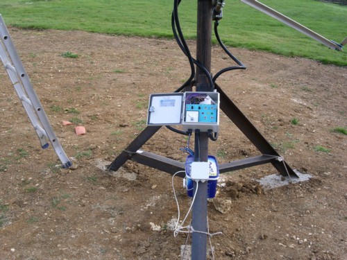
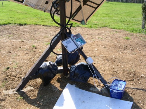
the control box and sensor array |
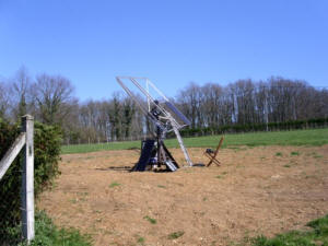
Wire up the control box |
Hated doing this bit but was well worth
doing |
 |
 |
 |
 |
|
So, after the desktop planning fit the
lower solar panels |
Easy |
The top panels were harder to do as I
couldn't reach them !!! |
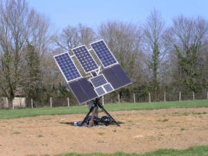
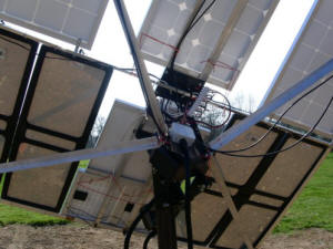
Mechanically complete with sandbags as
extra ballast |
 |
 |
 |
 |
|
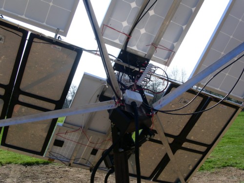
Wire up the solar panels |
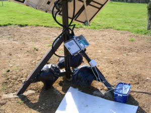
Check the control box functions |
Connect the array to the battery cables |
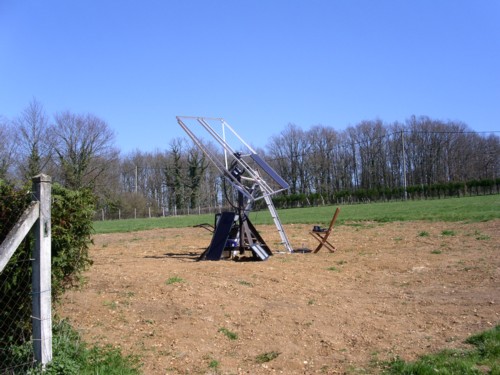
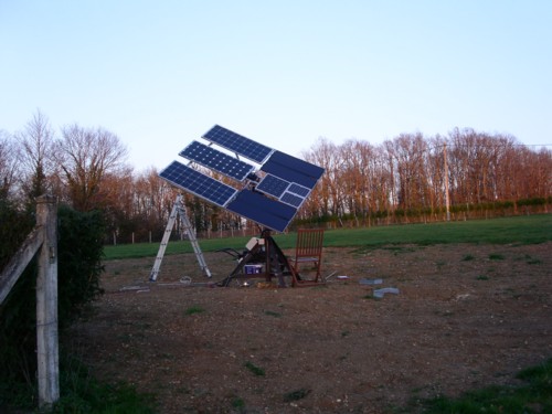
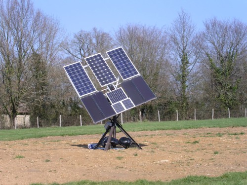
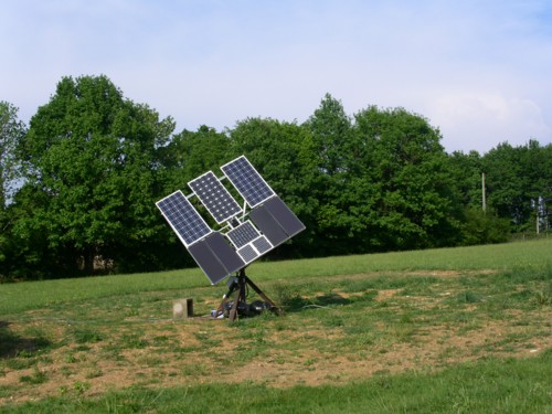
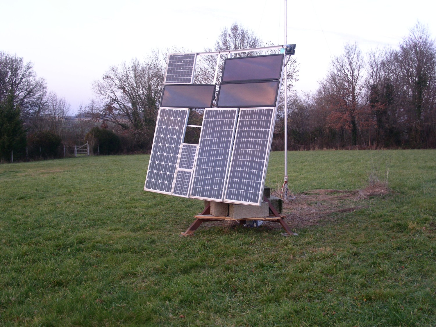
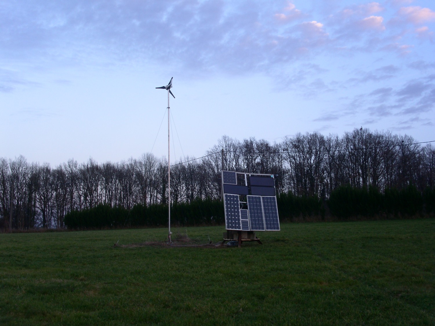
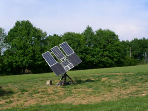
And one fully functioning solar tracker |
|
Results: The array amounts to
about 300 watts of panels collected from various sources over the
years. Some panels are only 10 watts. The latest top big
ones are 80 watts each. |
I have seen this array charging the
battery pack at 18.5 amps. As the panels track the sun this
output is sustainable for most of the day. |
NEXT: Modify the inclination mechanical
arrangement as this does not function correctly when the panels are
East or West. It just skews the panels sideways. |
This is due to the original task of the
motor arrangement, tracking satellites. |
 |
 |
 |
 |
| 16
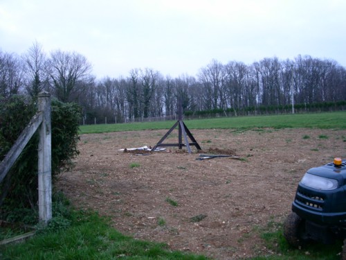
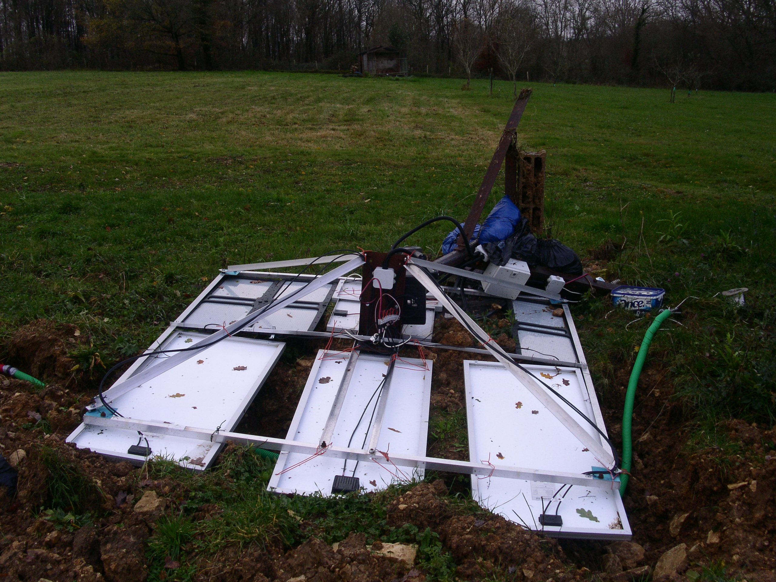
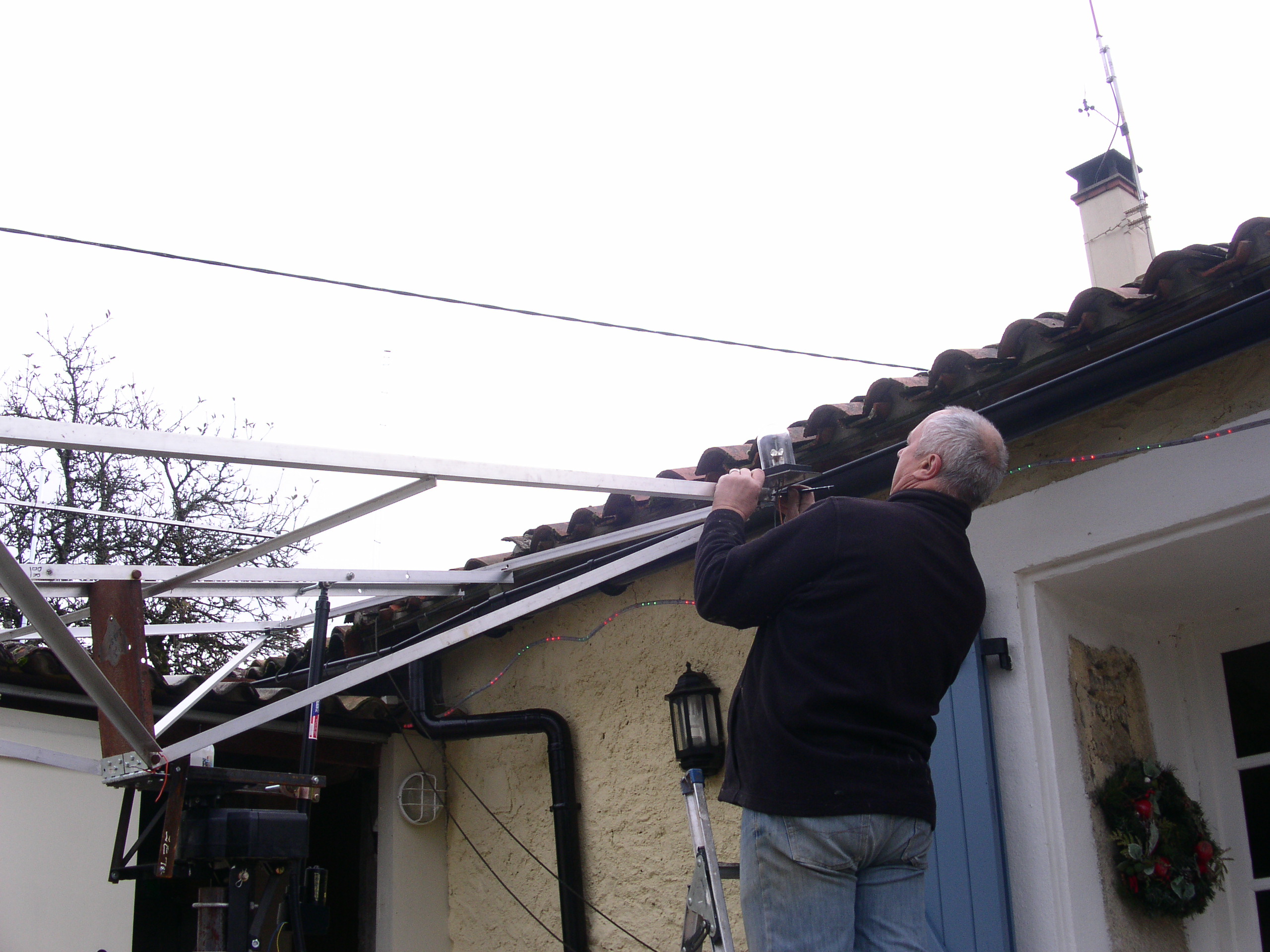
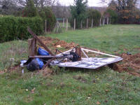
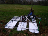
December 2011 and a violent storm rips through the Vienne toppling
over the tripod which had 3*40kg bags of sand sat on the base cross
members and each leg was attached to a concrete building block
buried in the ground. You can see one of the blocks hanging from the
top leg. |
All that
was damaged was one 15watt solar panel and the dome covering the sun
detector was smashed. Could have been a lot worse and very much more
expensive if more panels had required replacing. |
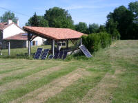
Temporary placement of solar panels to at least catch some solar
power and keep my battery bank topped up whilst I decided what to do
with the damaged tracker |
As
previously mentioned, the inclination part of the tracker did not
function correctly when pointing East or West and it took me ages
thinking about what I could do to correct this problem. 16th
November 2013 and I've worked it out and worked up my enthusiasm so
|
 |
 |
 |
 |
| 16
November 2013 - back to the garage with the tracker
where I can work
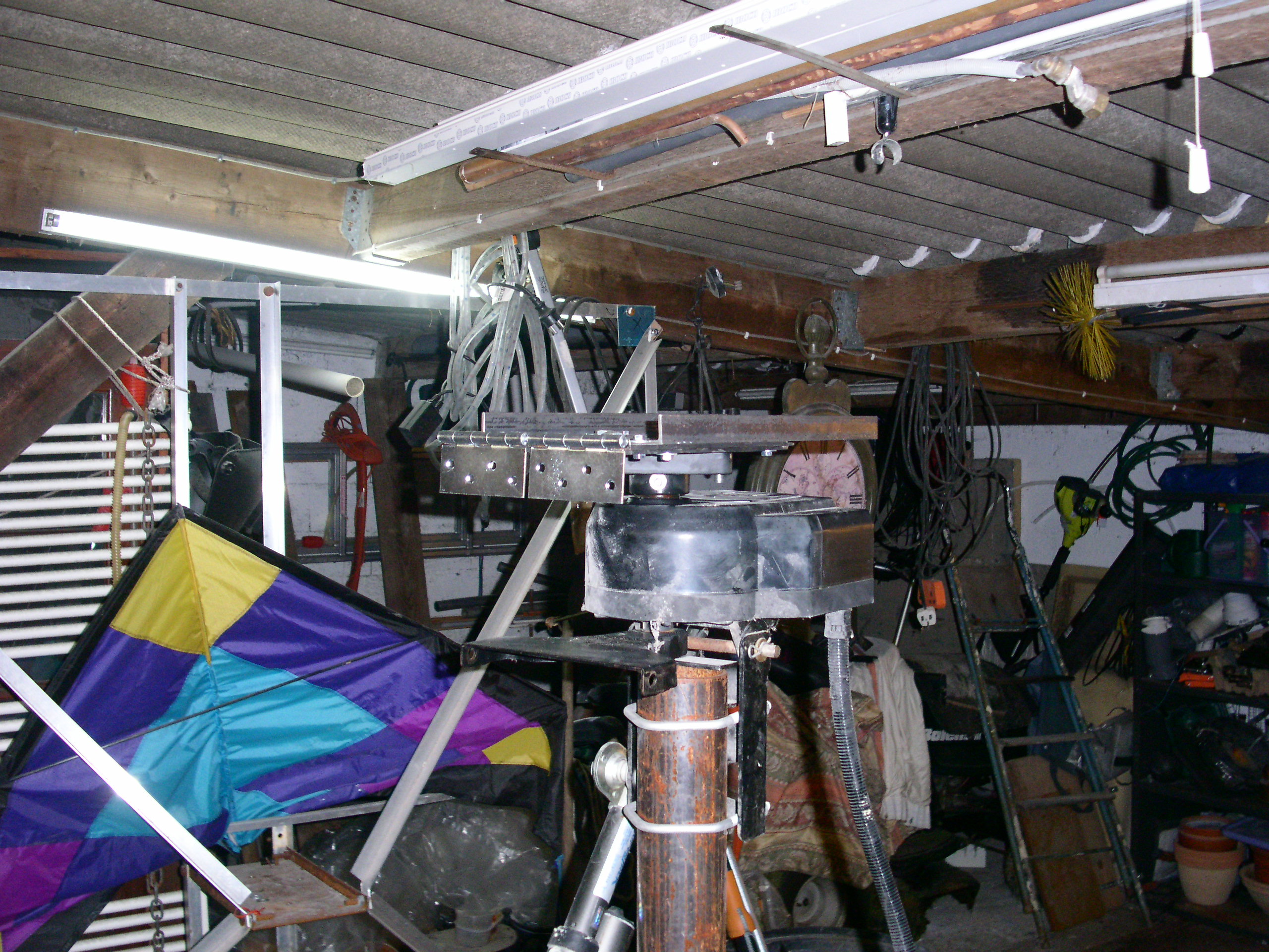
on it in the dry with all the tools close by |
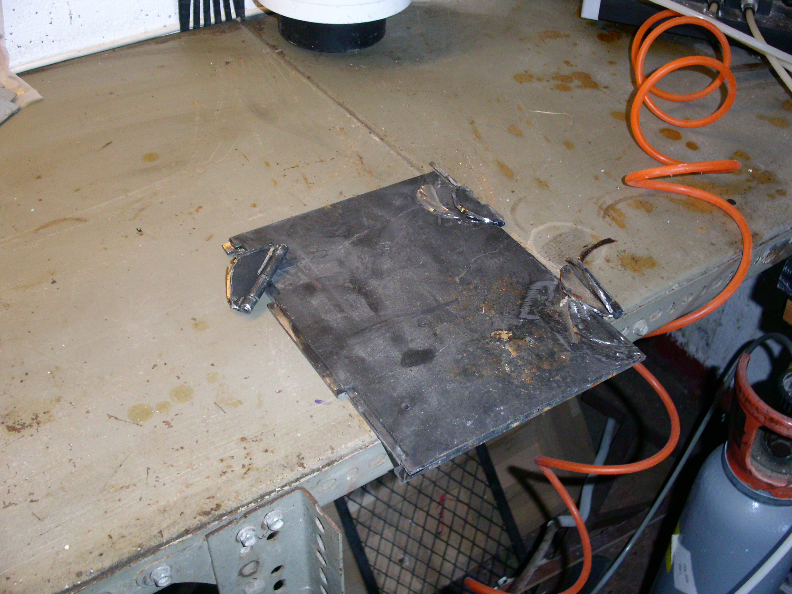
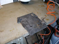
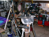
The idea is to
use a new top plate on the motor and hinge this to the solar panel
frame old head plate. Two old plates from the pellet boiler
installation will form the new head plate. Grind off the
hinges |
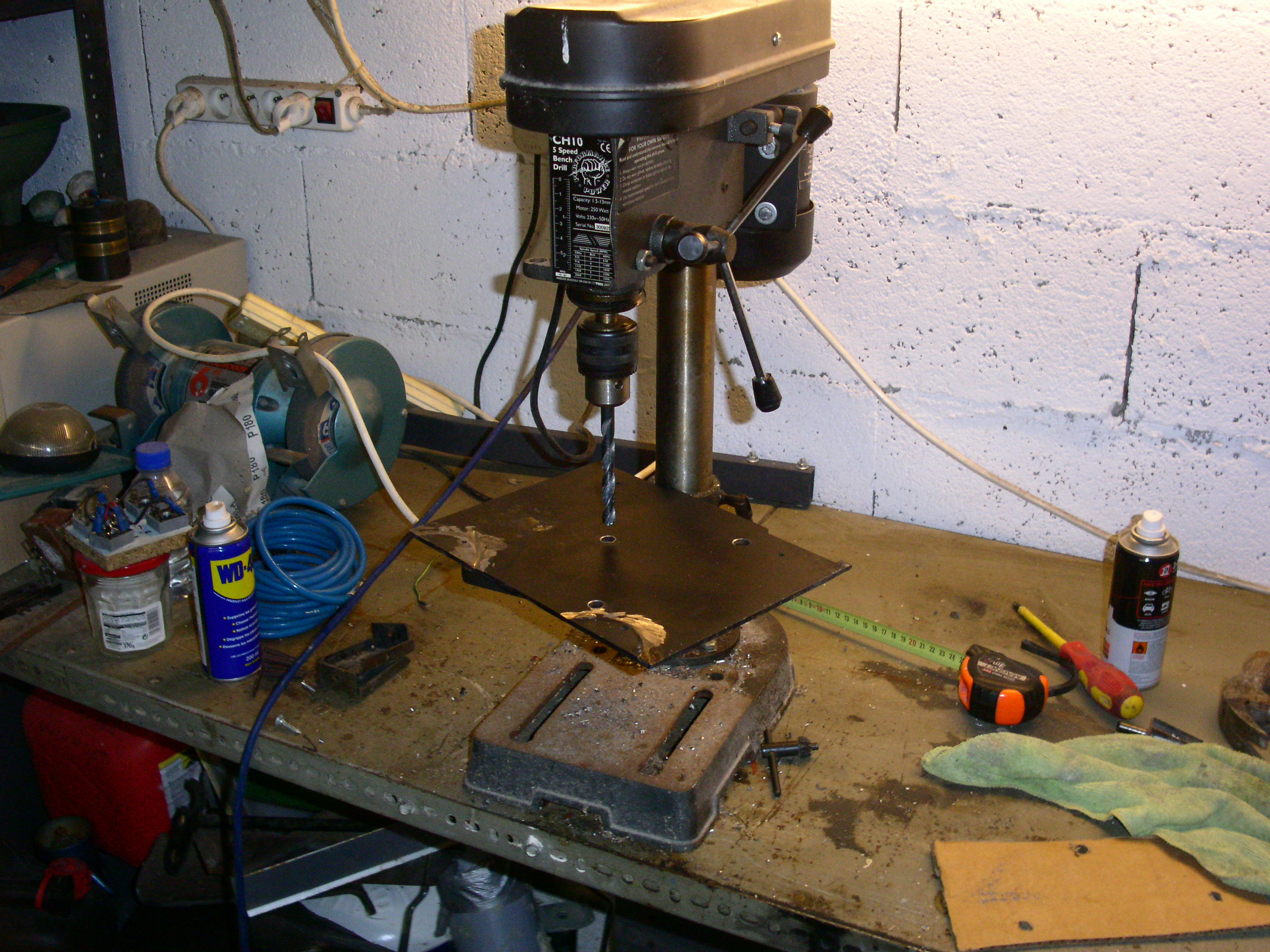
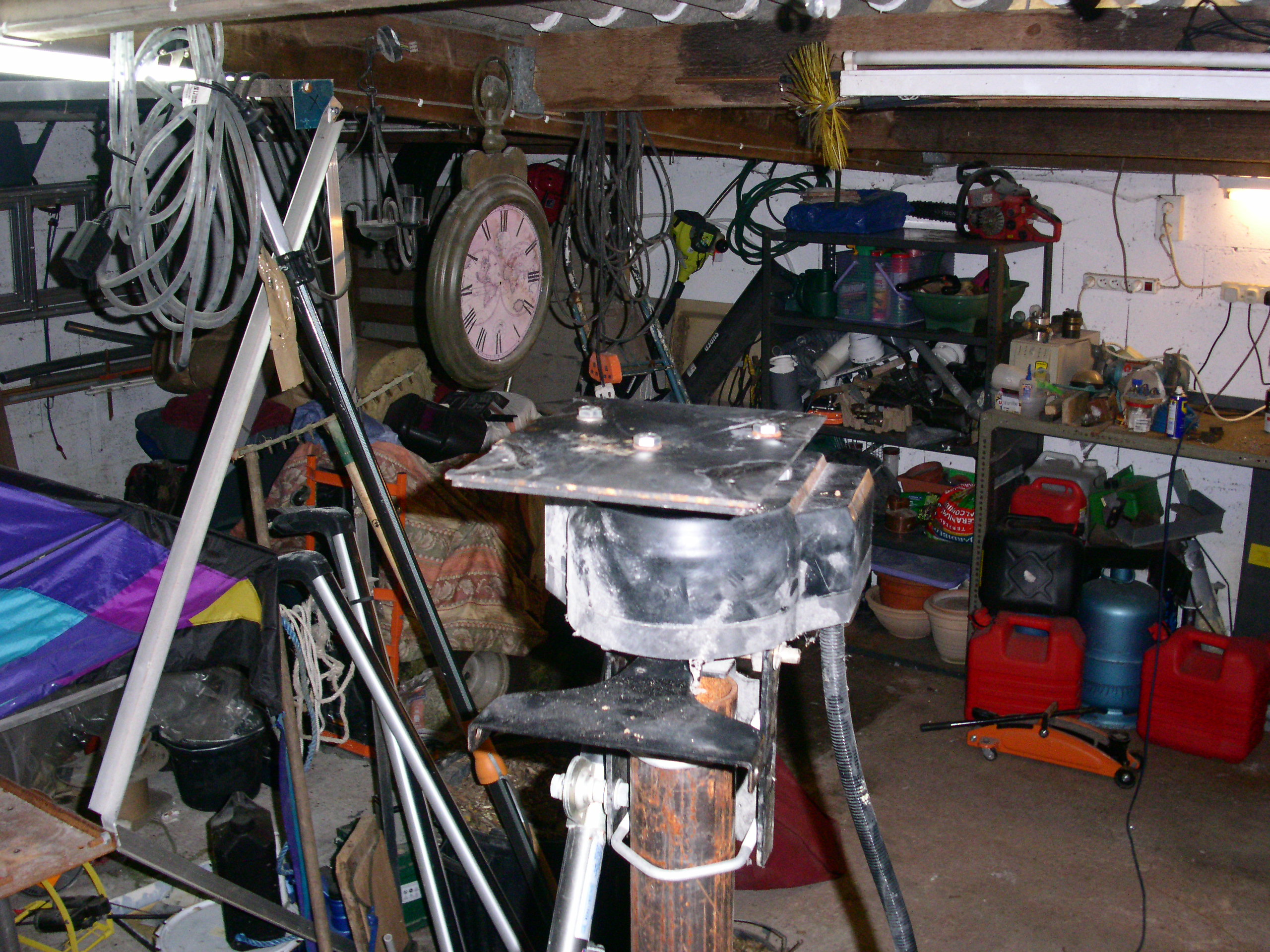
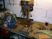
26 Nov - Mark and drill
holes in new top head plate to fix it to the motor head plate |
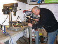
Spot and drill
holes in the second plate. I'm hoping two plates will be strong
enough |
 |
 |
 |
 |
|
Check both plates
fit correctly |
Centre punch
hinge holes in head plate |
Time for a rest!
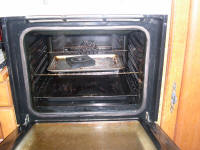
Bake the sun sensor mounting block in the oven @ 235 degrees C to
|
soften the
araldite so that the broken glass from the old dome can be removed
|
 |
 |
 |
 |
|
Yeah!! It worked |
27 Nov - Back to real work
- fit hinges to new head plate |
Cut to length new
angle iron side bars for head plate ( I do miss the power hacksaw at
SETA) |
Spot and drill
bars |
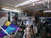 |
 |
 |
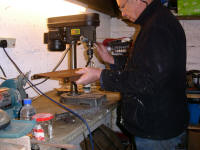 |
|
Fit new side bars |
28 Nov - Remove original
head plate from solar panel frame |
Measure, drill
and fit new inclination fixed bar replacing the screw jack.
Keeps the motor unit level |
Spot and drill
hinges in old head plate |
 |
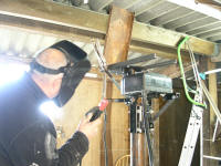 |
 |
 |
|
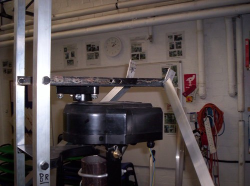
14 Dec - Bolt old head
plate to hinges |
Fit side stays
between top and bottom head plates and weld cross stay |
Move the whole
lot outside because there is not enough head room in the garage to
fit the solar panel frame |
Refit old head
plate to solar panel frame |
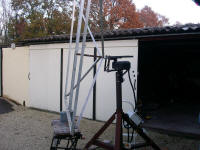 |
 |
 |
 |
|
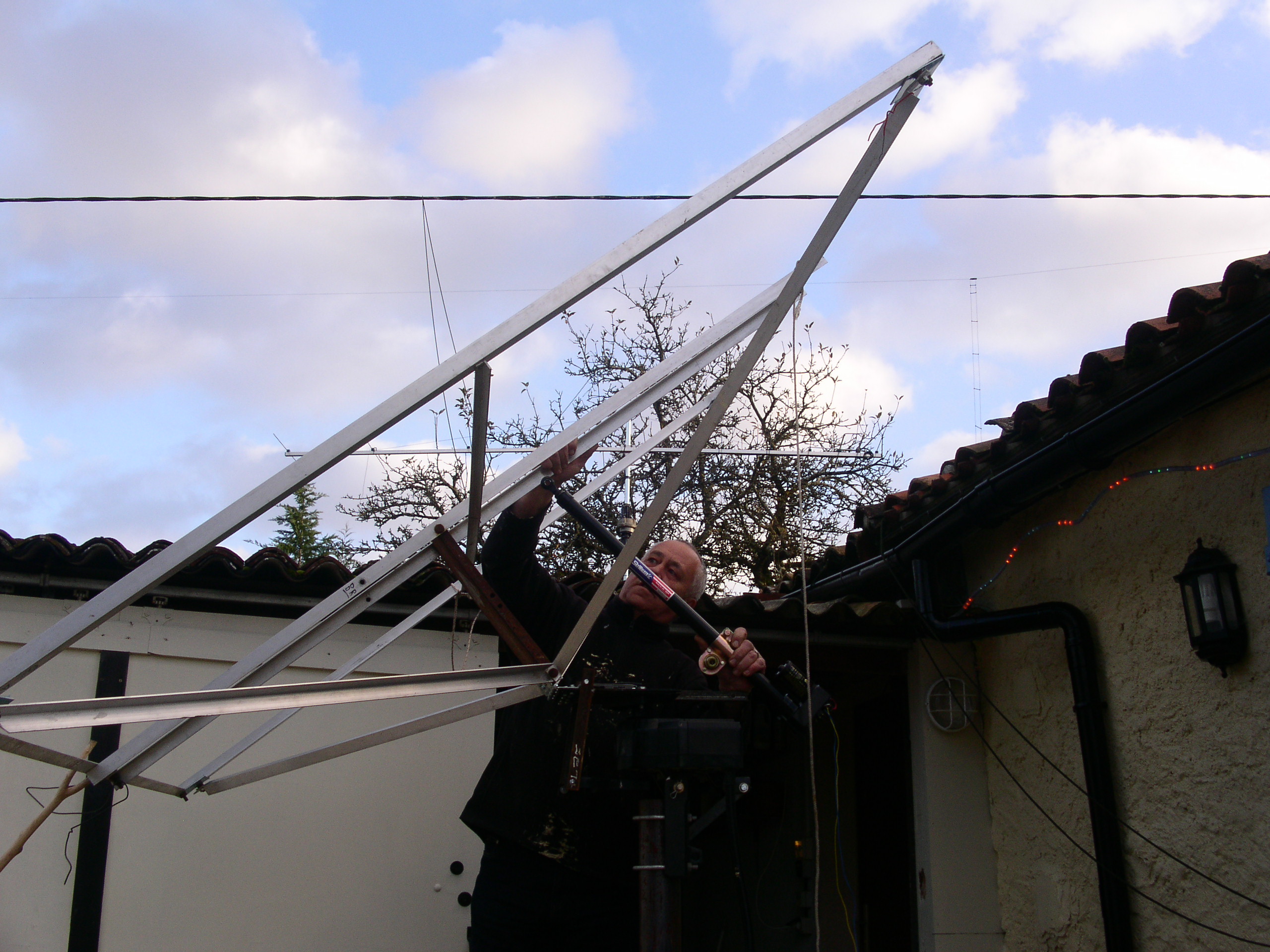
Now the elevation
bit should work correctly. It's not looked like this for 2 years!! |
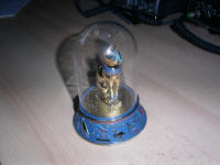
15 December -
Another bloody sacred cat thingy, the second one I've bought from
e-bay |
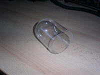
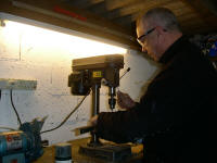
I only require
the dome bit |
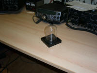
but at least it's
a purffect fit!! |
 |
 |
 |
 |
|
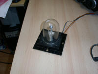
18 Dec - Sun
detector wired up and dome hot glued into position |
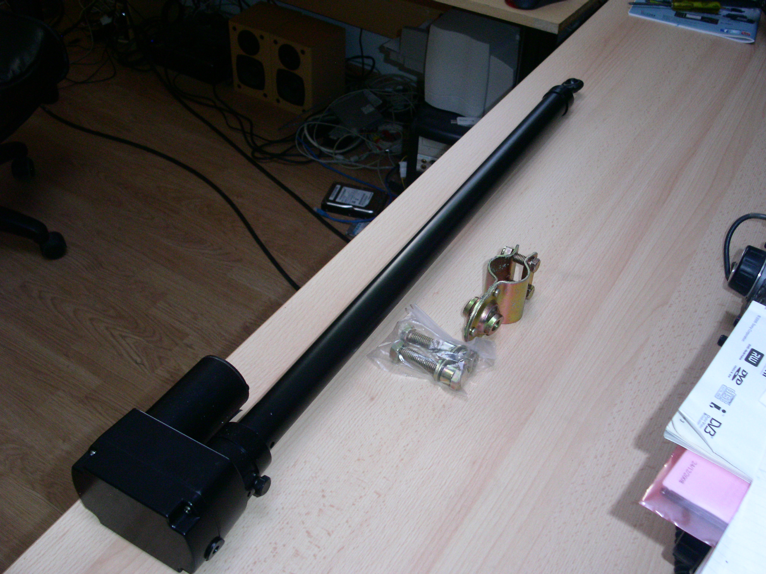
19 Dec - New
Screwjack for elevation. I could not work out how to do this
with a 4.5 inch jack s ordered a 24 inch one |
Marking screwjack
mounting holes in solar panel framework |
Drilling holes
for Screwjack mounting on head plate angle iron |
 |
 |
 |
 |
|
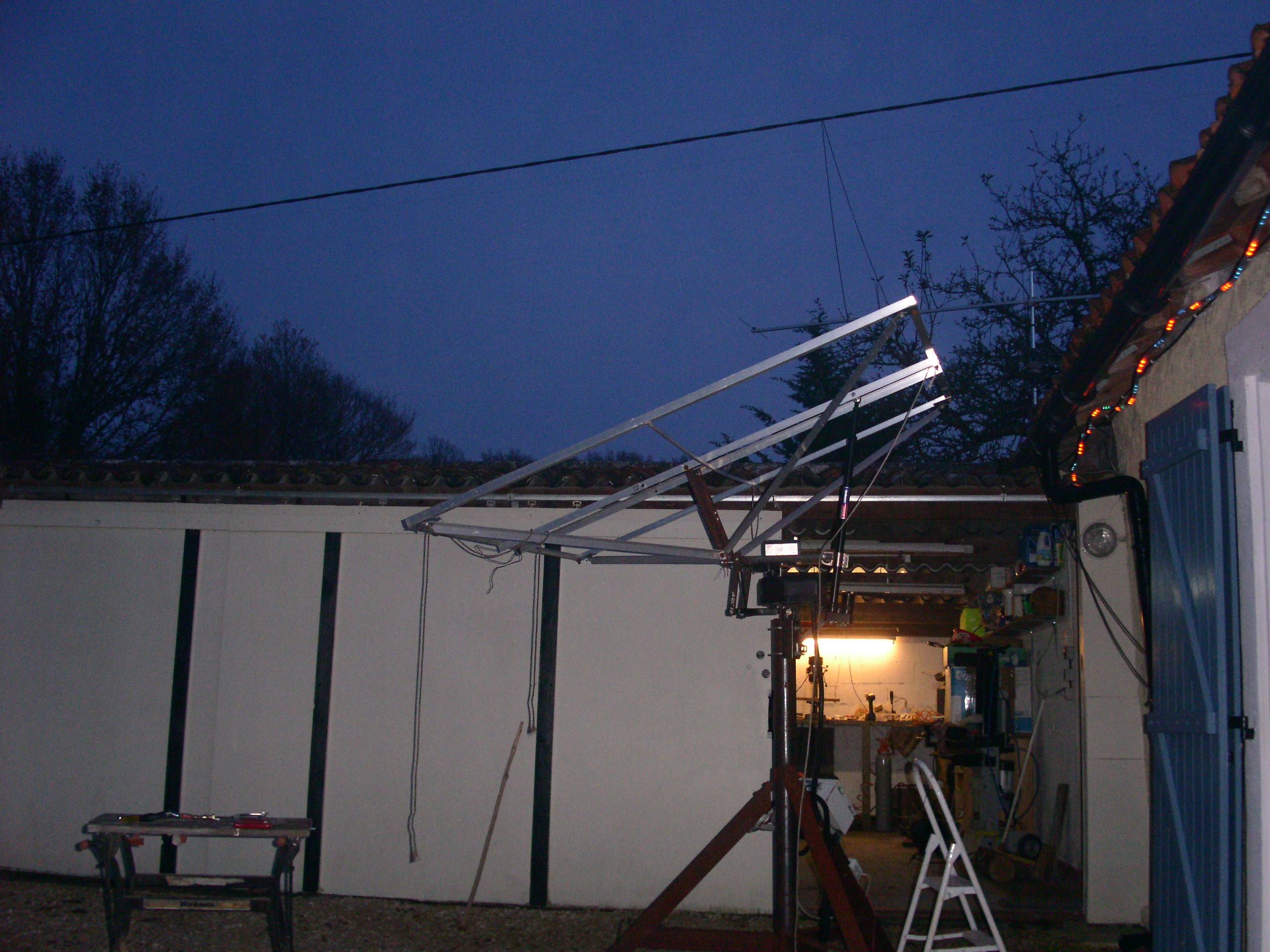
Drill the holes |
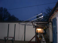
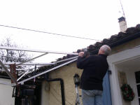
and hey presto!!
vertical for sun rise and sun set |
and 70 degrees
elevation for summer mid day |
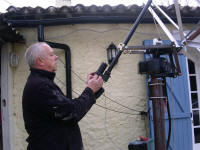
21 Dec - Marking
sun detector mounting holes |
 |
 |
 |
 |
|
Drilling detector
mounting holes |
Adjusting azimuth
limit switches |
adjusting
elevation limit switches |
Cutting some
spare iron that was laying around |
 |
 |
 |
 |
|
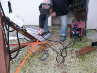
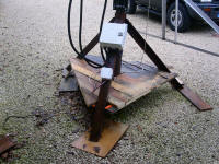
to weld to the
tripod so that I can add extra ballast to |
try and stop it
blowing over in the wind |
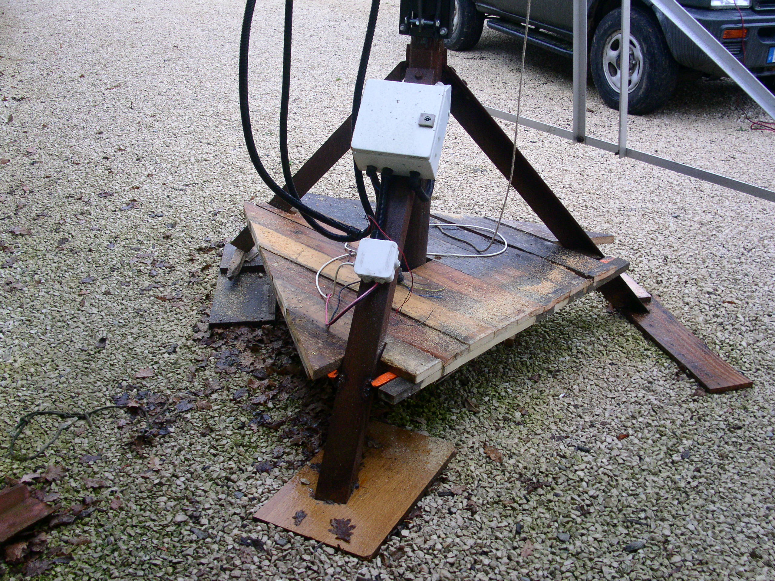
1st Jan 2014 - fit a wooden base for
me to sit on and to hold the building blocks |
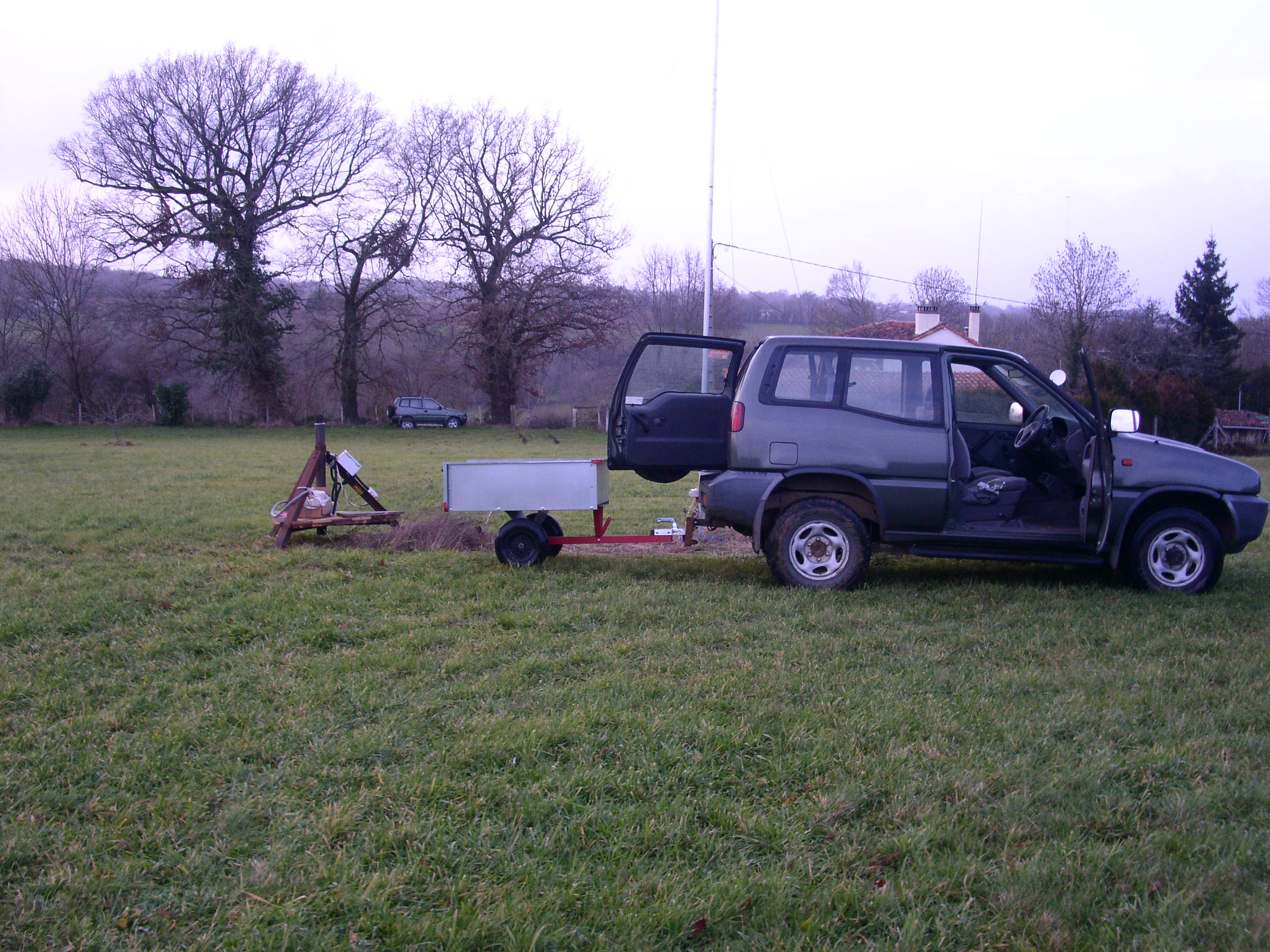
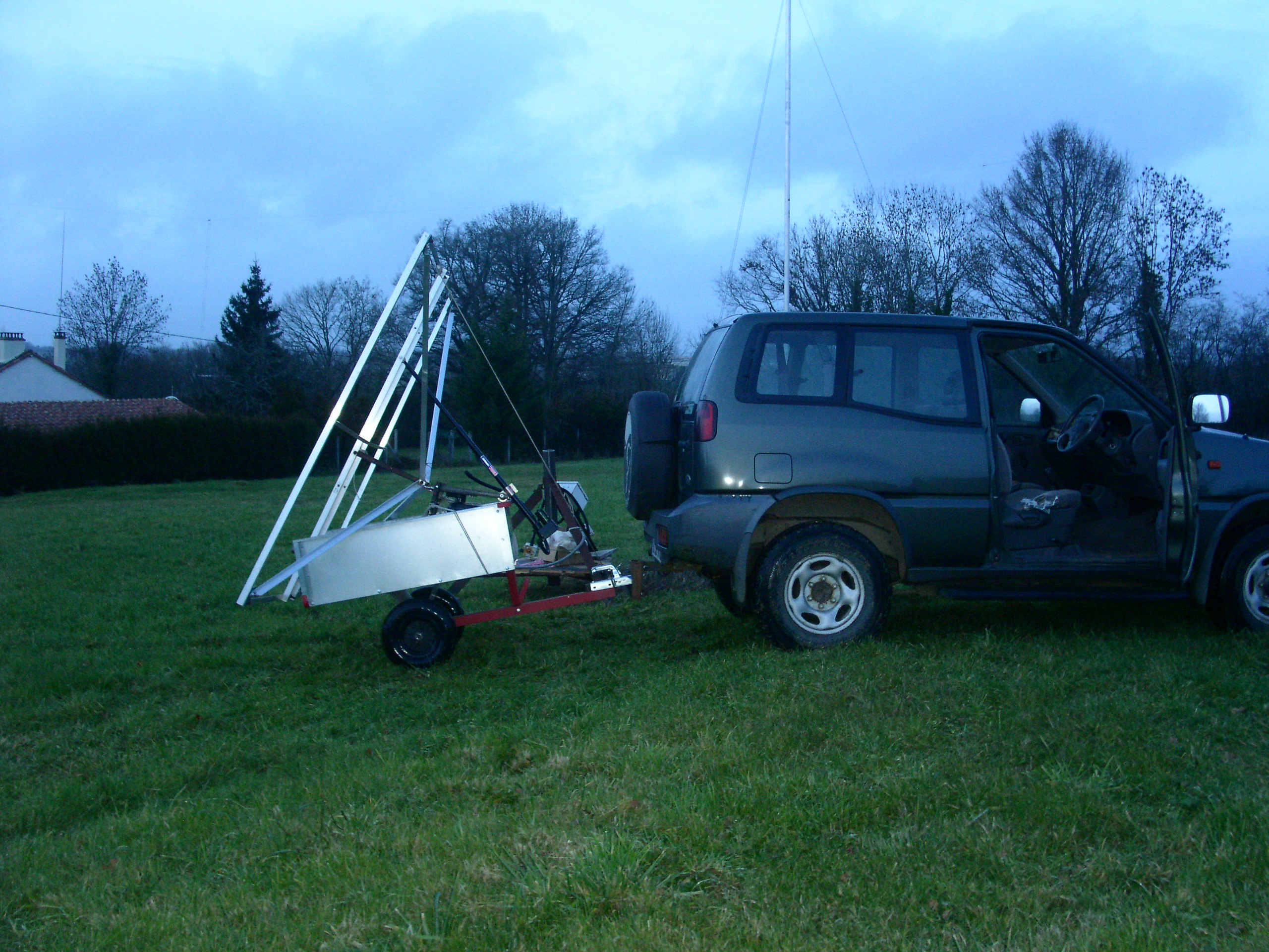
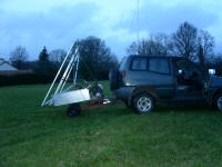
2 Jan - Trailer and Maverick |
 |
 |
 |
 |
|
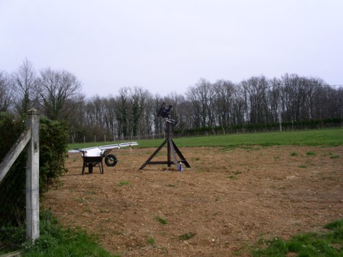
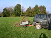
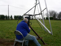
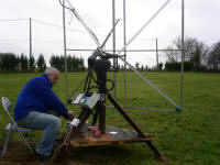
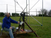
and take the tripod base up the field |
to it's final resting place |
load up the solar panel frame and
motor units |
God knows how I would have managed
without the 4*4 |
 |
 |
 |
 |
|
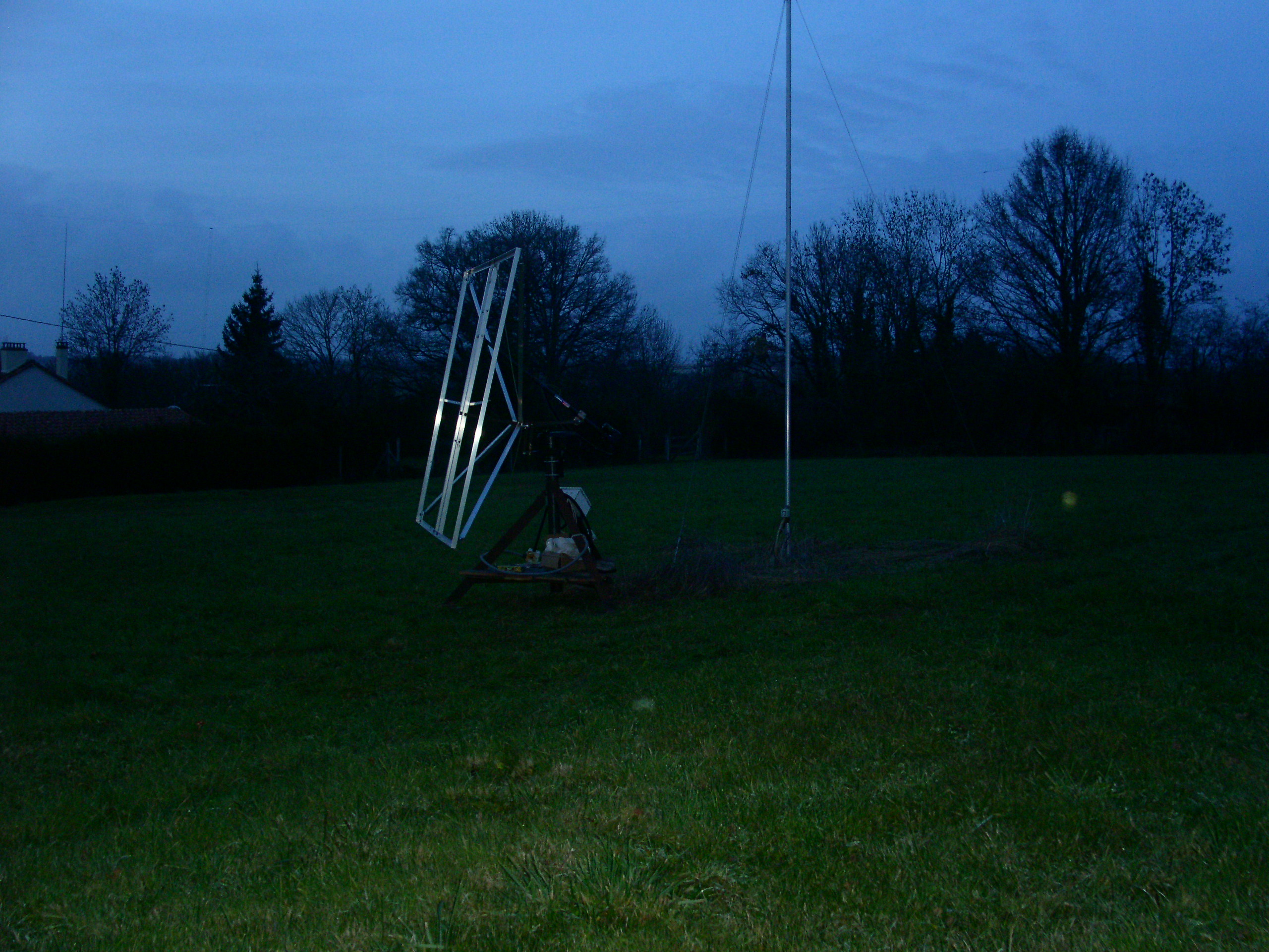
2 Jan @ 17:35 and it's back in place |
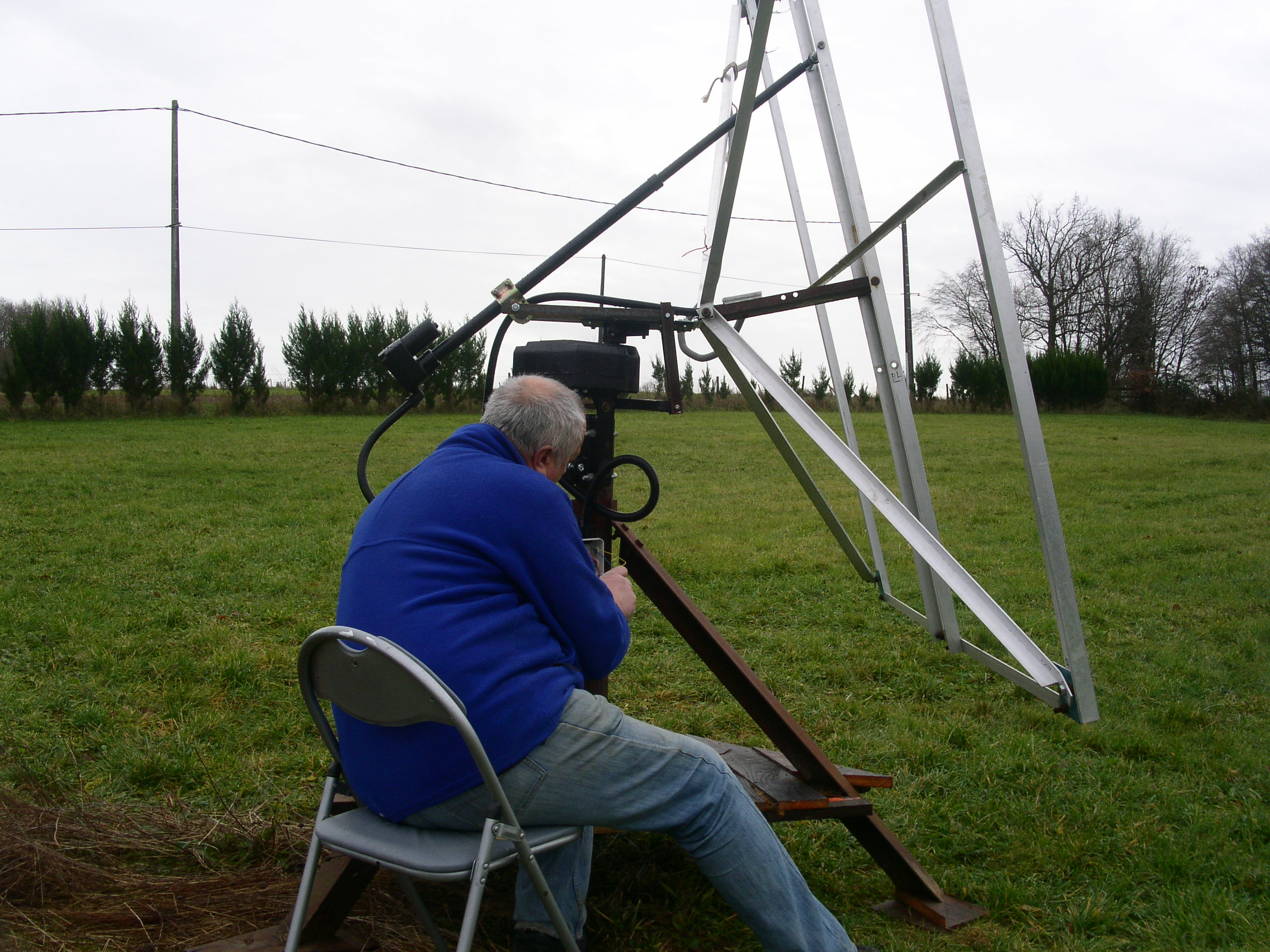
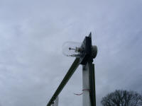
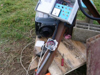
5 Jan - wire up the the two motor
cables |
and check it moves east and west when
it should do |
and up and down when it should |
 |
 |
 |
 |
|
Only managed to get one concrete
block up the field in the wheel barrow. |
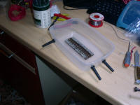
So much for the hot glue gun. Dome
has come away from the base. |
So, back to good old Araldite |
Let's hope this holds |
 |
 |
 |
 |
|
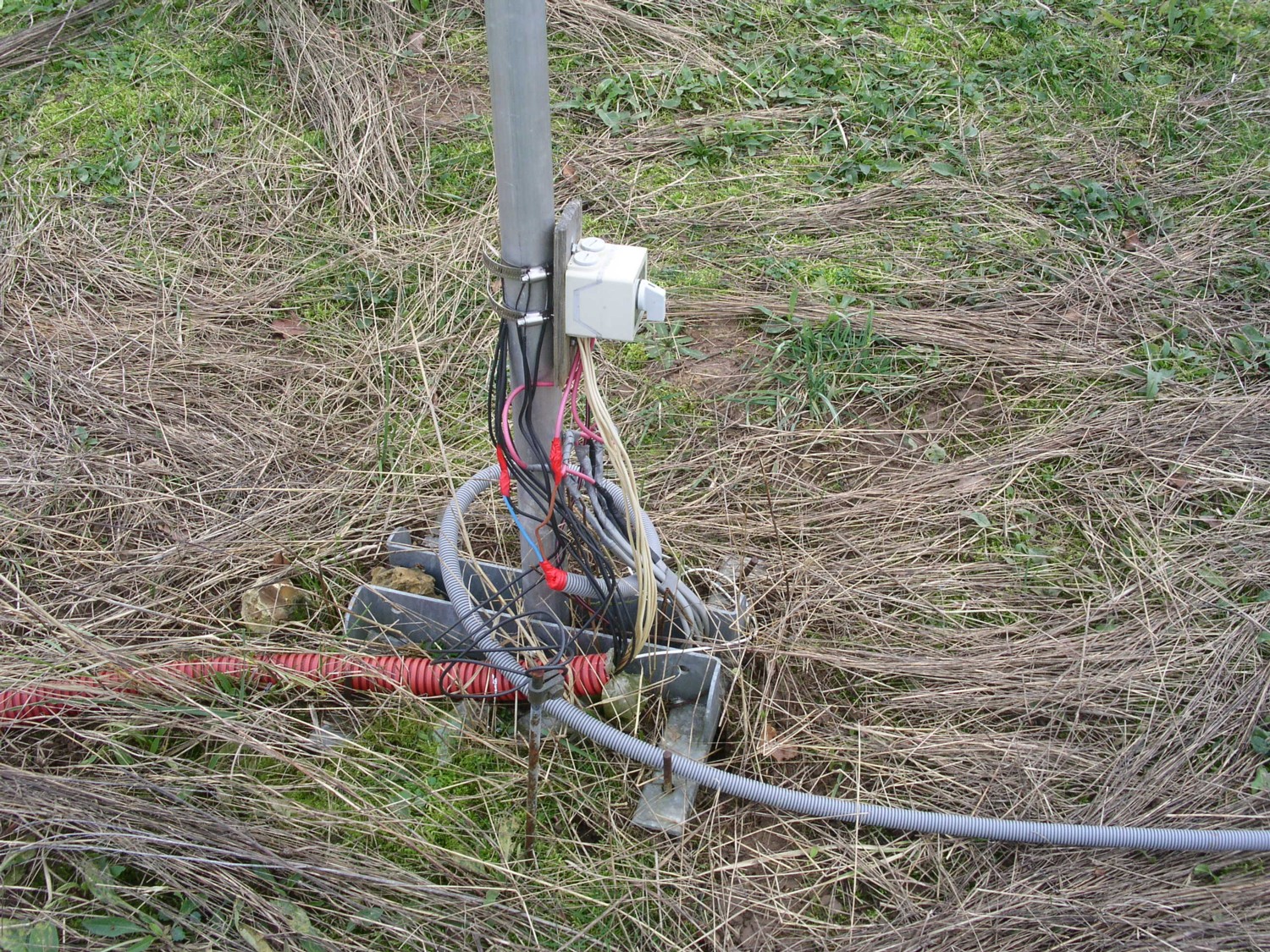
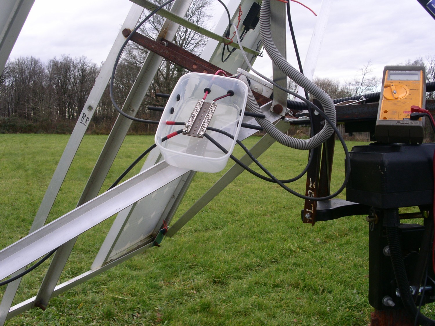
6 Jan - New junction box for solar
panel cables |
7 Jan - Connect
control box to junction box |
and then junction
box to 12 volt main battery feed |
Fit new solar
panel junction box |
 |
 |
 |
 |
|
and start fitting
the solar panels |
10 Jan - and then
connect them up |
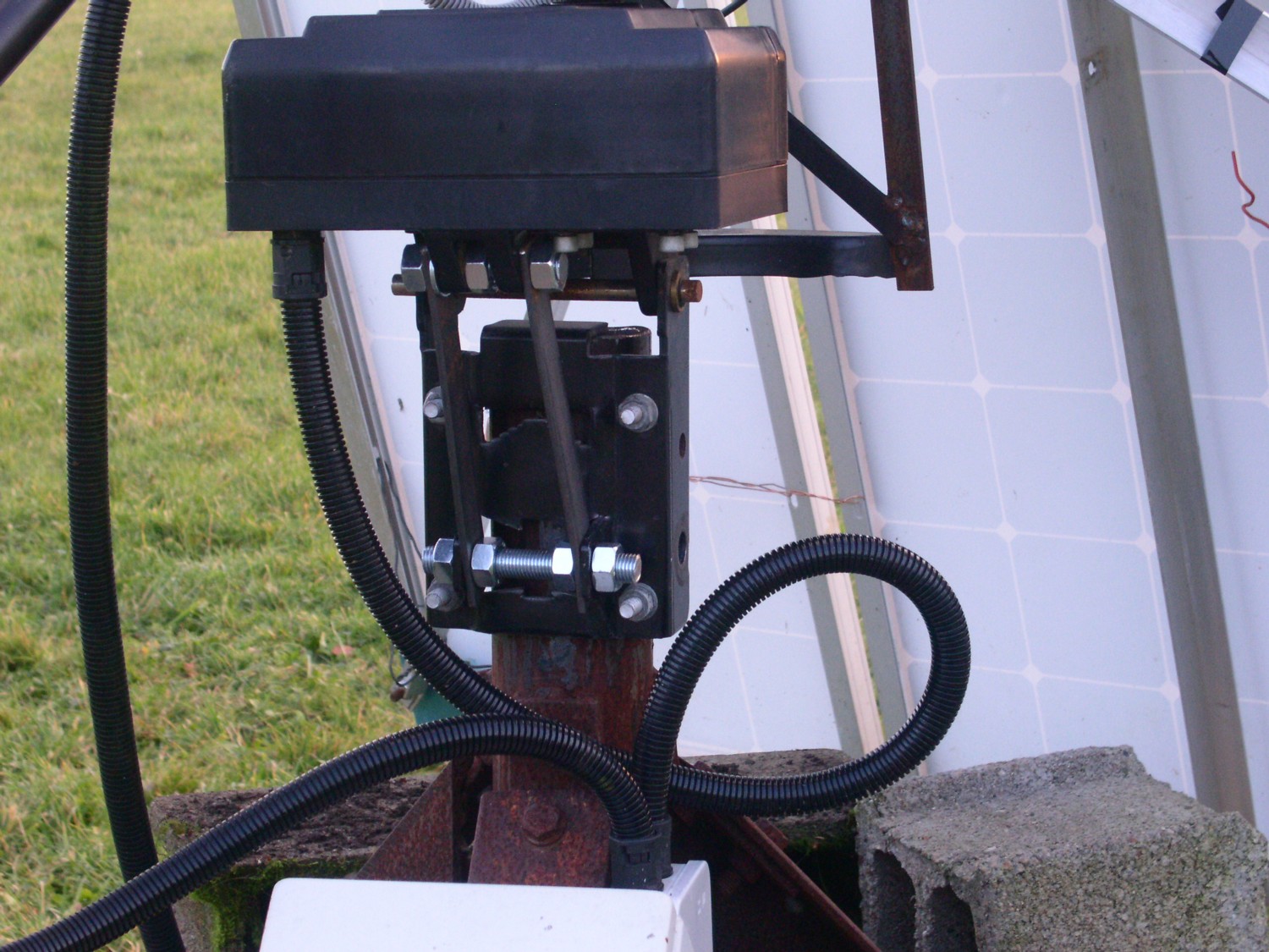
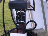
I had to redesign
the fixed inclination arrangement as the bolts were bending. 2
bars and bigger studding. |
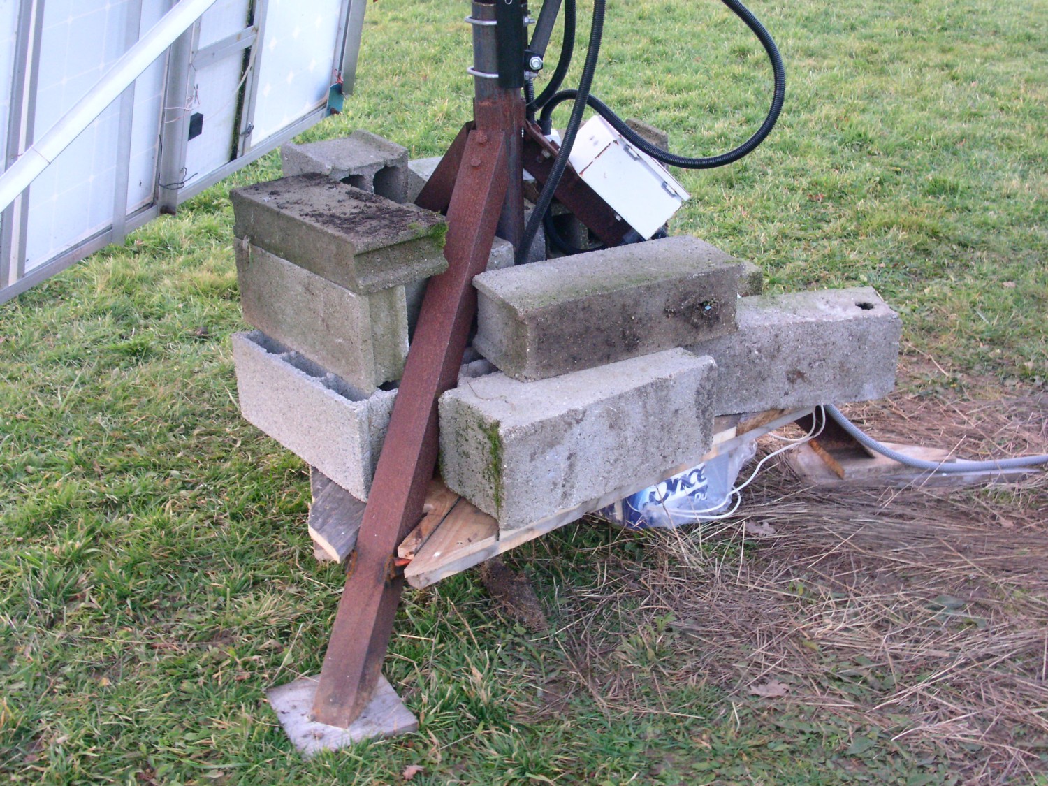
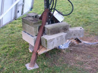
Concrete blocks
as ballast to try and prevent the tripod being blown over by the
wind. |
 |
 |
 |
 |
|
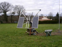
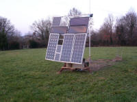
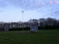
All panels fitted |
and wired up |
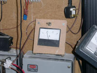
All controls
operational |
and, most
important, charging at 10 amps. |