
|
|
|
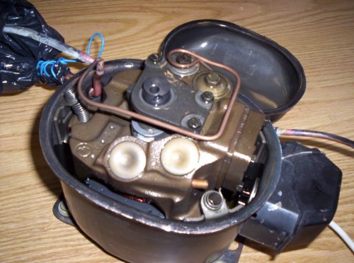
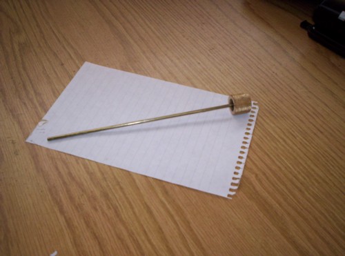
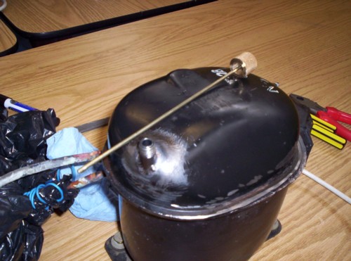
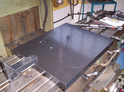
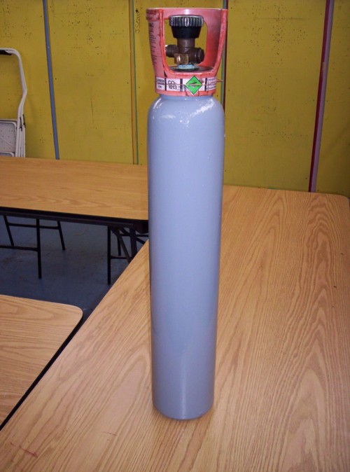
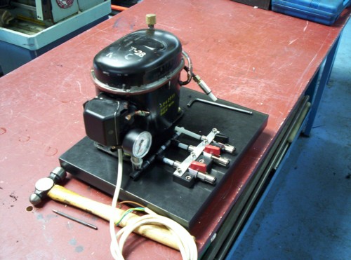
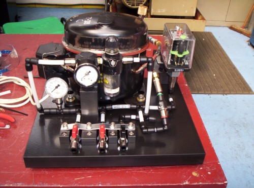
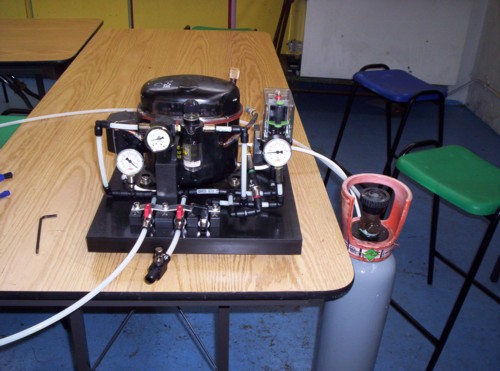
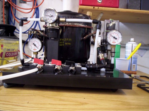
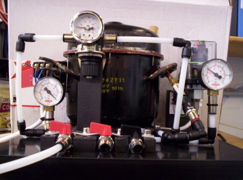
Compressor Project Having obtained a 12 metre pump up mast for hanging antennas on I decided I needed a quieter compressor than the B&Q one I bought a few years ago. I had heard people talking about converting fridge compressors and, knowing how quiet they are, thought it would be a great idea. WARNING - DO NOT ATTEMPT THIS This is a record of how I converted an old fridge compressor unit and is presented here purely for interest. I do not advise or encourage anyone to follow what I have done. I strongly advise against carrying out such a conversion. Refrigerator compressors and their associated pipe work contain refrigerant gases which can be under high pressure. High pressure gas is dangerous. In addition to the high pressure some of these gases can be very dangerous to your health especially if inhaled. The only people who should carry out this type of work are competent refrigeration engineers. The objective was to produce a compressor which was quiet to run and would supply about 20 psi for a SCAM 12 pump up mast. It needed to look after itself and switch on as seldom as possible. The pressure switch to operate the motor cuts in at 30 psi and cuts out at 90 psi. The left hand red valve connects to the reservoir gas bottle at 90 psi. The middle red valve can be used for either connecting to the noisy higher volume compressor, in case extra air volume is required, or for supplying 90 psi to something else. The right hand black valve is the regulated supply to the mast.
|